Thermal Imaging Camera
You can connect a thermal imaging camera to the Raspberry Pi 5 on a quadcopter to build thermal images and determine precise temperatures at individual points within the frame.
Principle of Operation
The thermal imaging camera detects infrared radiation emitted by surrounding objects. A dedicated sensor converts thermal radiation into electrical signals. The camera’s electronics use these signals to determine the temperature distribution and produce a thermal image of the object.
The thermal imaging module used here has a resolution of 256x192 pixels and returns two frames: a processed thermal image and a temperature matrix.
Data in ROS 2
The clover2_thermal driver splits the frame received from the camera into a thermal image and a temperature matrix. With the default settings, these are published to two topics with the sensor_msgs/msg/Image message type:
Topic |
Encoding ( |
Content |
|---|---|---|
|
|
Processed grayscale thermal image. Each pixel contains a brightness value from 0 to 255. |
|
|
Temperature matrix. Each pixel contains a temperature in degrees Celsius as a 32-bit floating-point number. |
Both images measure 256×192 pixels. Each pixel in the thermal image corresponds to an element of the temperature matrix at the same coordinates. Use image_viz to view the image and temperature to obtain temperature values.
How to Install the Camera
The thermal imaging camera can be mounted on the quadcopter using one of two methods.
Method 1: Front-facing Mount
Install the thermal imaging camera into the provided mount.

Camera in the mount
Secure the mount (with the camera installed) onto the guard arcs, as shown in the figure below.

Mount installed to the quadcopter guard arcs
Connect the USB cable from the kit to the camera.
Plug the other end of the USB cable into an available USB port on the Raspberry Pi 5.
Secure the cable using zip ties to ensure it remains clear of the propeller rotation area.
Method 2: Horizontal Mount
Install the thermal imaging camera into the provided mount.
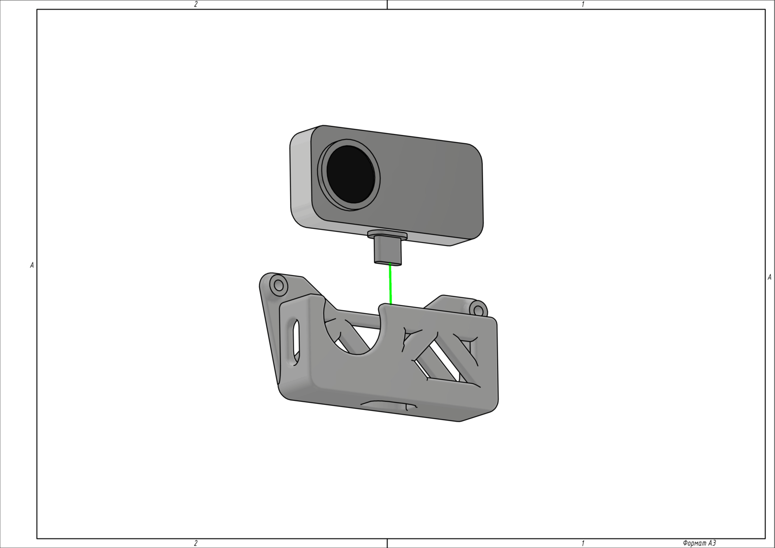
Camera in the mount
Secure the mount to the bottom deck using M3x8 screws, as shown in the figure.
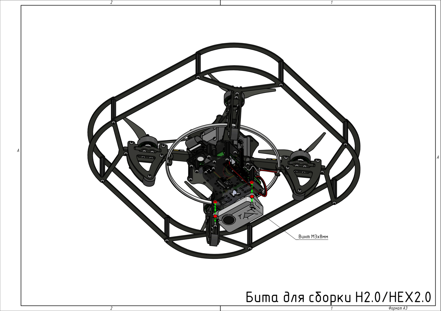
Mount secured to the bottom deck
Connect the USB cable from the kit to the camera.
Plug the other end of the USB cable into an available USB port on the Raspberry Pi 5.
Secure the cable using zip ties to ensure it remains clear of the propeller rotation area.
Configuration
Launching via clover2-settings
To enable the thermal imaging camera in Clover, open the settings:
Launch the node using the following command:
clover2-settings
Select the additional_sensors group, as shown in Figure 5.
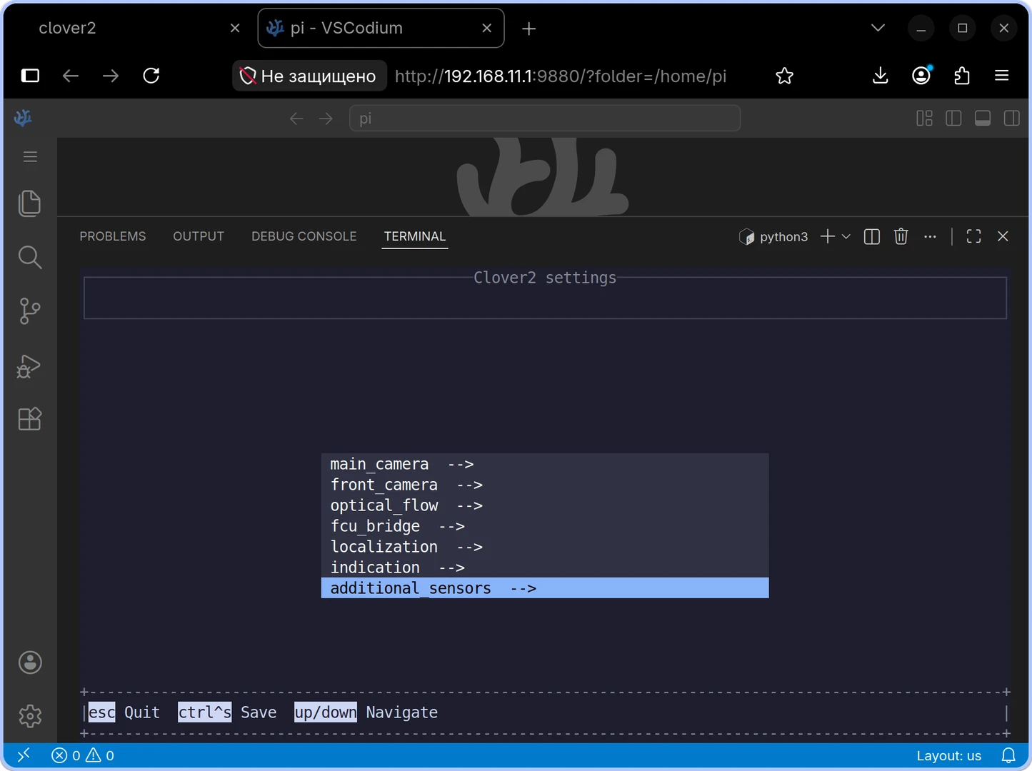
Figure 5 — Selecting the additional_sensors group in clover2-settings
In the additional_sensors group, select the thermal_camera setting (see Figure 6) and enable it by setting its value to true.
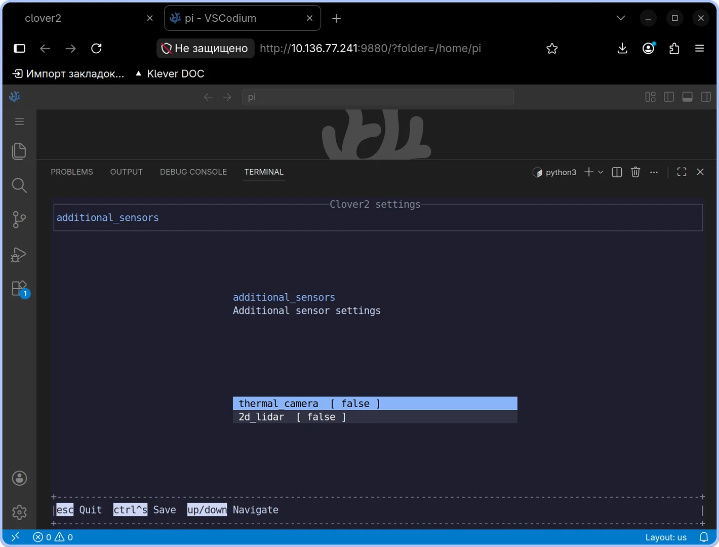
Figure 6 — Selecting the thermal_camera option
Press Ctrl+S to save the changes. A confirmation will appear, as shown in Figure 7.
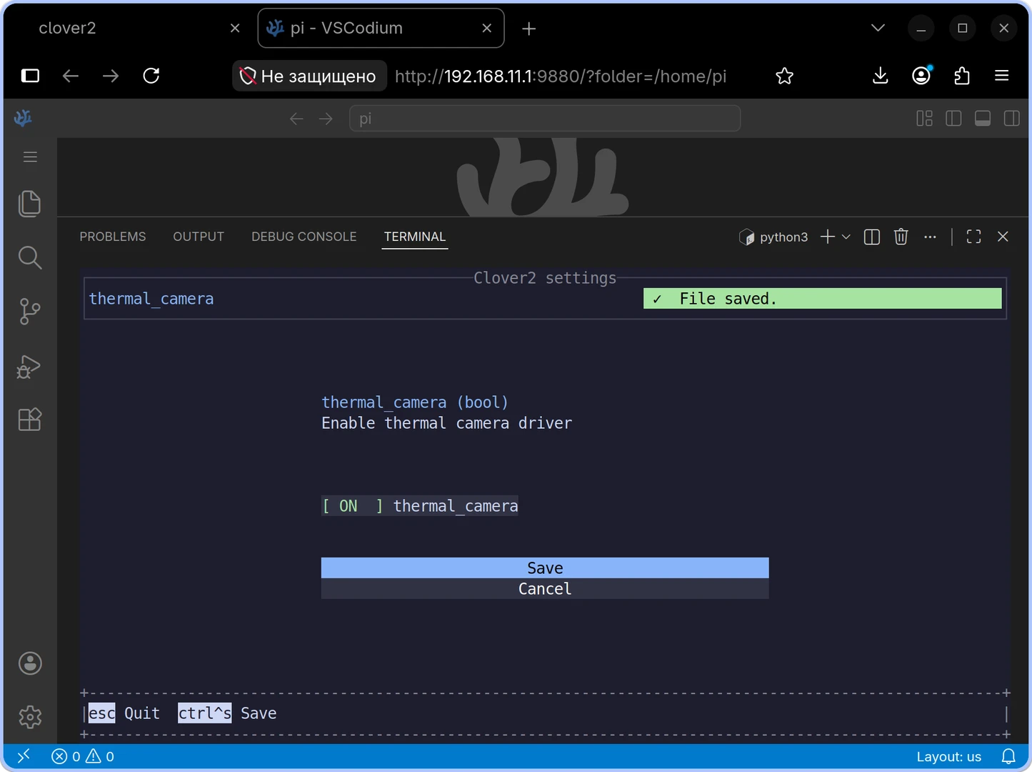
Figure 7 — Saving the thermal imaging camera setting
Then press Esc several times to exit the application. Restart the clover2 service:
sudo systemctl restart clover2
Once the driver starts successfully, it will publish frames to the /thermal_camera/image_viz and /thermal_camera/temperature topics.
Usage
In Python, you can obtain the temperature matrix using the Clover2 client:
from clover2 import Clover2

drone = Clover2()
temperature = drone.thermal_camera.get_temperature()

# The NumPy matrix has shape (192, 256), with indices in [y, x] order.
print(f"Temperature at the center of the frame: {temperature[96, 128]:.2f} °C")
The pixel coordinate origin is at the top-left corner: x increases to the right and y increases downward. The get_temperature() method returns the most recently received NumPy matrix. On the first call, it waits up to 5 seconds for data and raises TimeoutError if none arrives. To obtain the original ROS message, use drone.thermal_camera.get_temperature_msg().