Clover 5 DEV
Contents
Fastener Sizes
Tip
Fasteners of various sizes are used during assembly. Installing screws or standoffs of the wrong size may result in damage to the quadcopter.
Cell 1 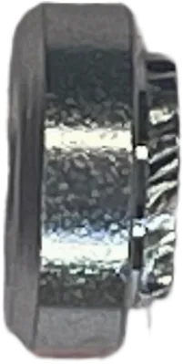
Press Nut M3 |
Cell 2 
Nylon Nut M3 |
Cell 3 
Nylon Standoff M2.5 |
Cell 4
Nylon Nut M2.5 |
Cell 5
Nylon Nut M2 |
Cell 6 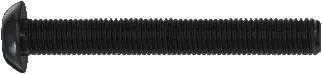
Screw M3x40 |
Cell 7 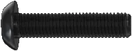
Screw M3x12 |
Cell 8 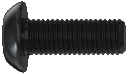
Screw M3x8 |
Cell 9 
Screw M3x6 |
Cell 10 
Screw M3x4 |
Cell 11 
Aluminum Standoff M3x40 |
Cell 12 
Damper Standoff M3 |
Cell 13 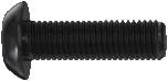
Screw M3x10 |
Cell 14 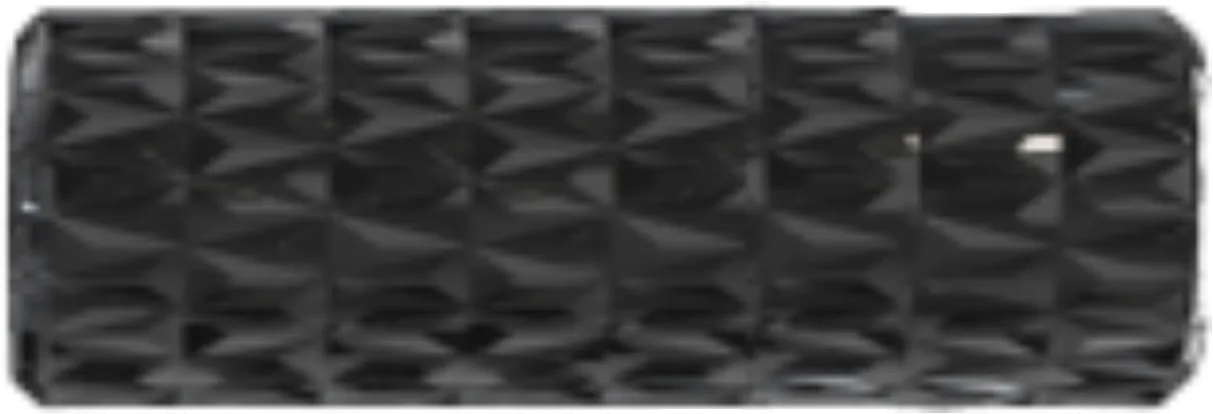
Aluminum Standoff M3x10 |
Cell 15
Aluminum Standoff M3x30 |
Cell 16 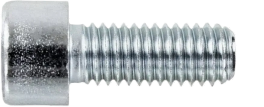
Screw M2x6 |
Cell 17 
Screw M2.5x4 |
Cell 18
Screw M2.5x6 |
Cell 19 
Self-tapping Screw M1.4x4 |
Cell 20
Screw M2x3 |
Cell 21 
Nylon Standoff M3x30 |
Cell 22 
Nylon Standoff M3x20 |
Cell 23 
Nylon Standoff M3x40 |
Cell 24 
Self-tapping Screw M1.4x10 |
Cell 25 
TPU Foot |
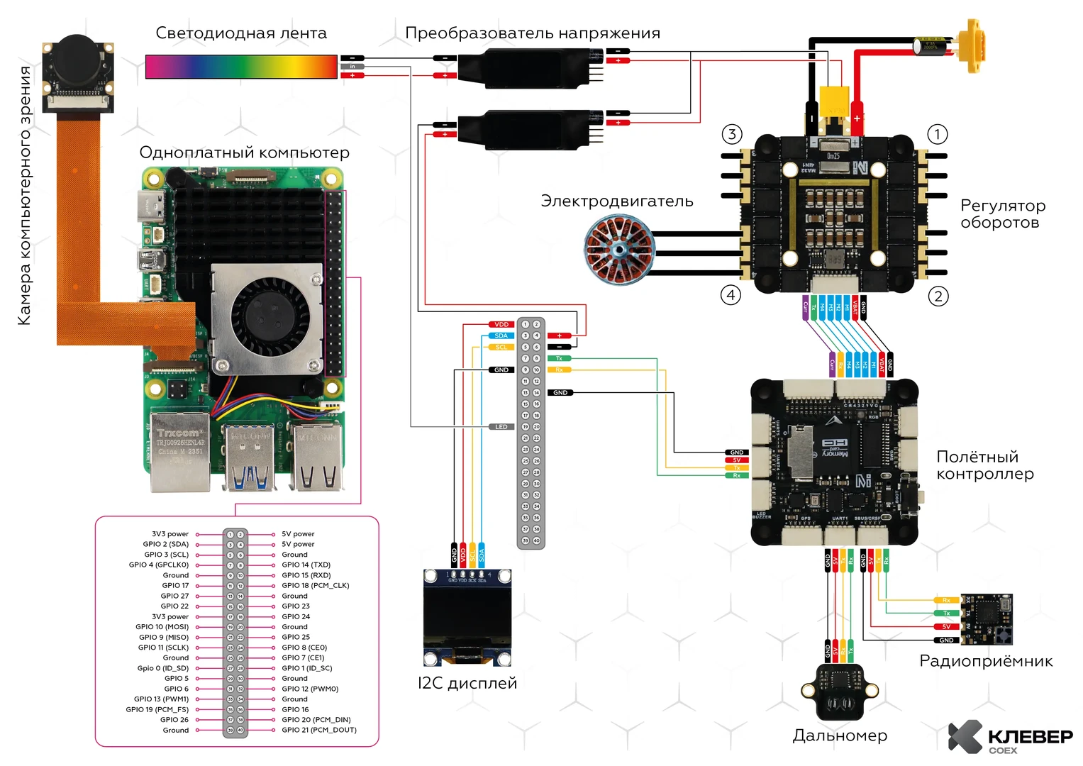
Wiring Diagram
Frame Assembly
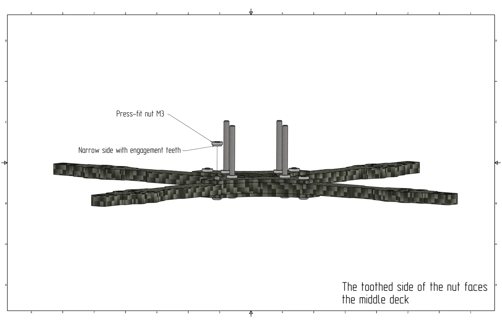
Align the 4 arms between the middle and bottom plates.

Install M3x12 screws (Cell 7) and M3x40 screws (Cell 6) from the bottom plate side: M3x12 (Cell 7) in the outer arm holes, M3x40 (Cell 6) in the central holes of the bottom plate.

Install M3 press nuts (Cell 1) on the middle plate and secure them with screws.
Motor and ESC Installation
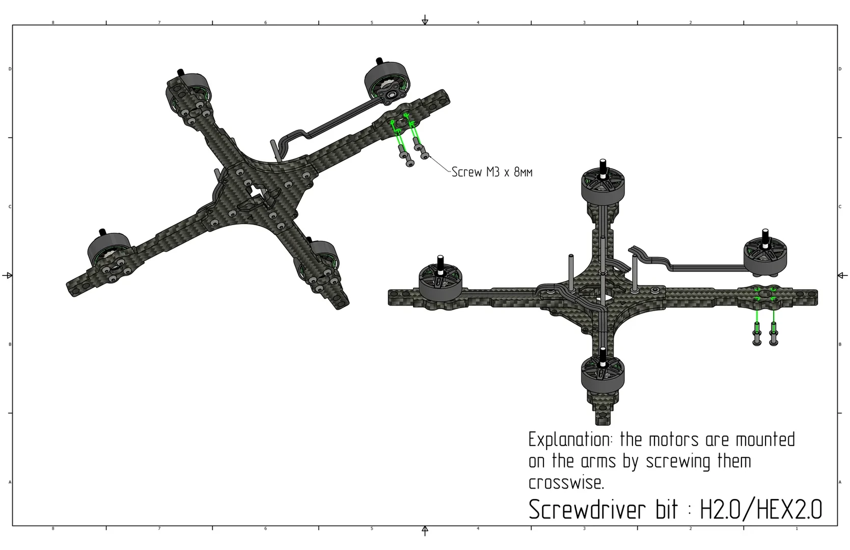
Install the motors into the corresponding holes on the arm using M3x8 screws (Cell 8).
Caution
Ensure that the motors are secured with M3x8 screws; otherwise, a short circuit between the windings may occur.
Install the motor wire protective covers on the arms.

On the top side of the ESC contacts, solder the power wires with a capacitor, put the protective cap on the wires, and solder the XT60 connector. On the bottom side of the ESC contacts, solder the XT30 connector.
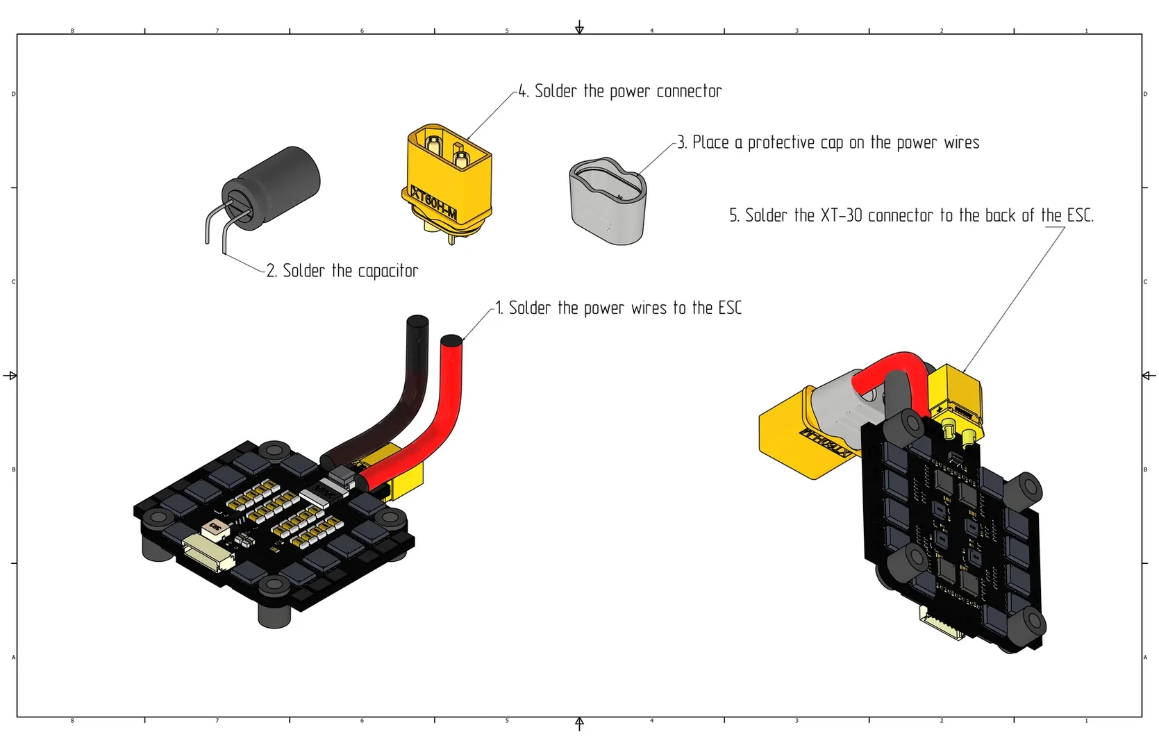
View of the ESC with the soldered capacitor and connectors.

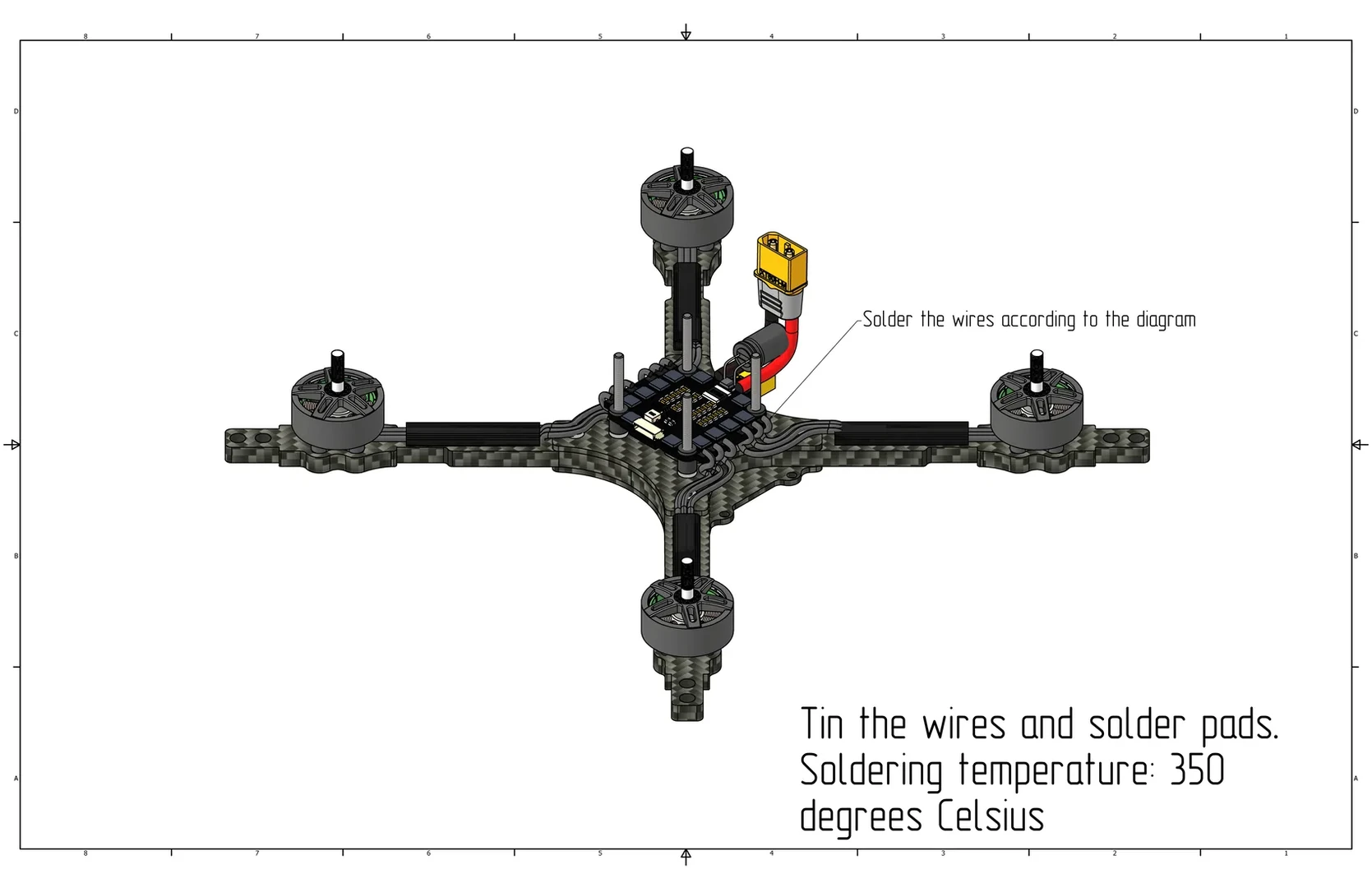
Install the ESC with the connector facing backward and solder the motors as shown in the image below.
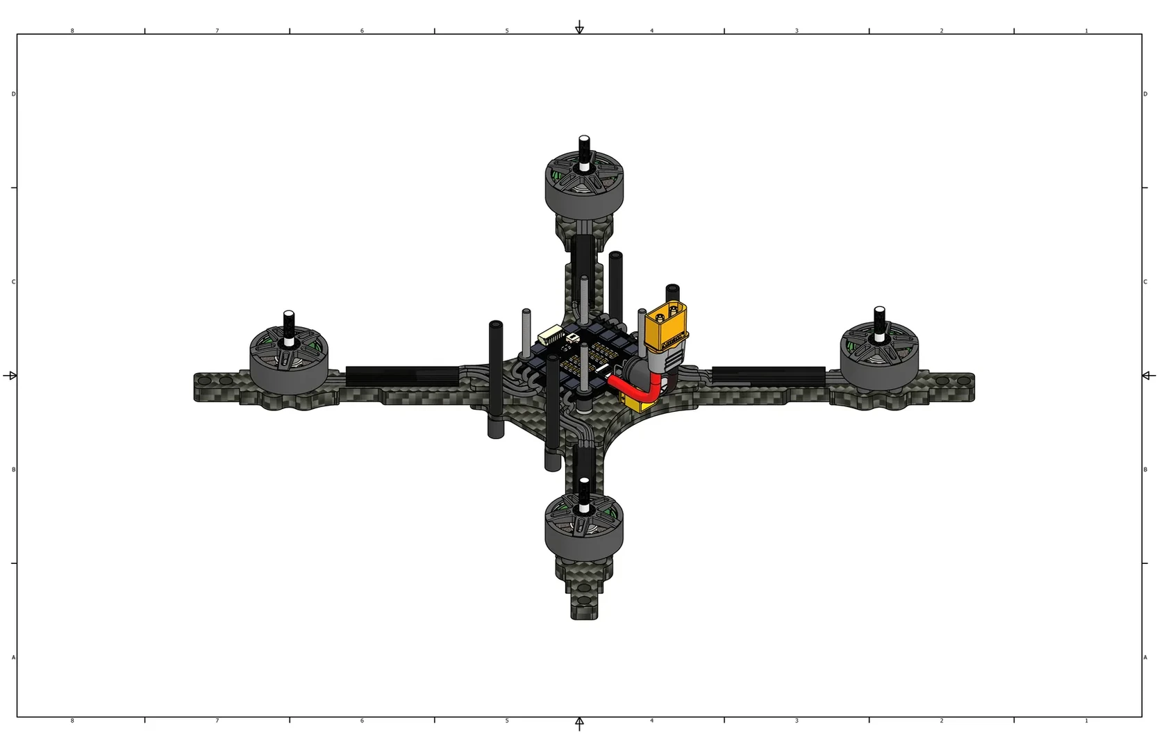
Aluminum Standoffs Installation

Flight Controller Installation
Before installing the flight controller, thread M3 nylon nuts (Cell 2) onto the M3x40 screws (Cell 6), then install the flight controller with the arrow pointing forward. Install nylon nuts to secure the flight controller.
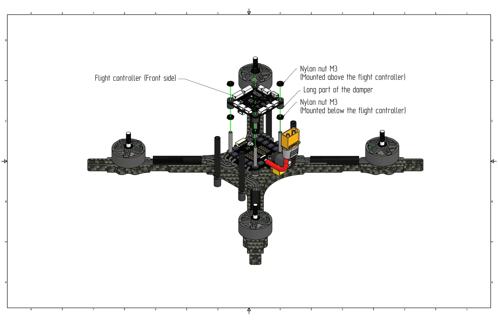
Install the 6-pin cable between the flight controller and the ESC.
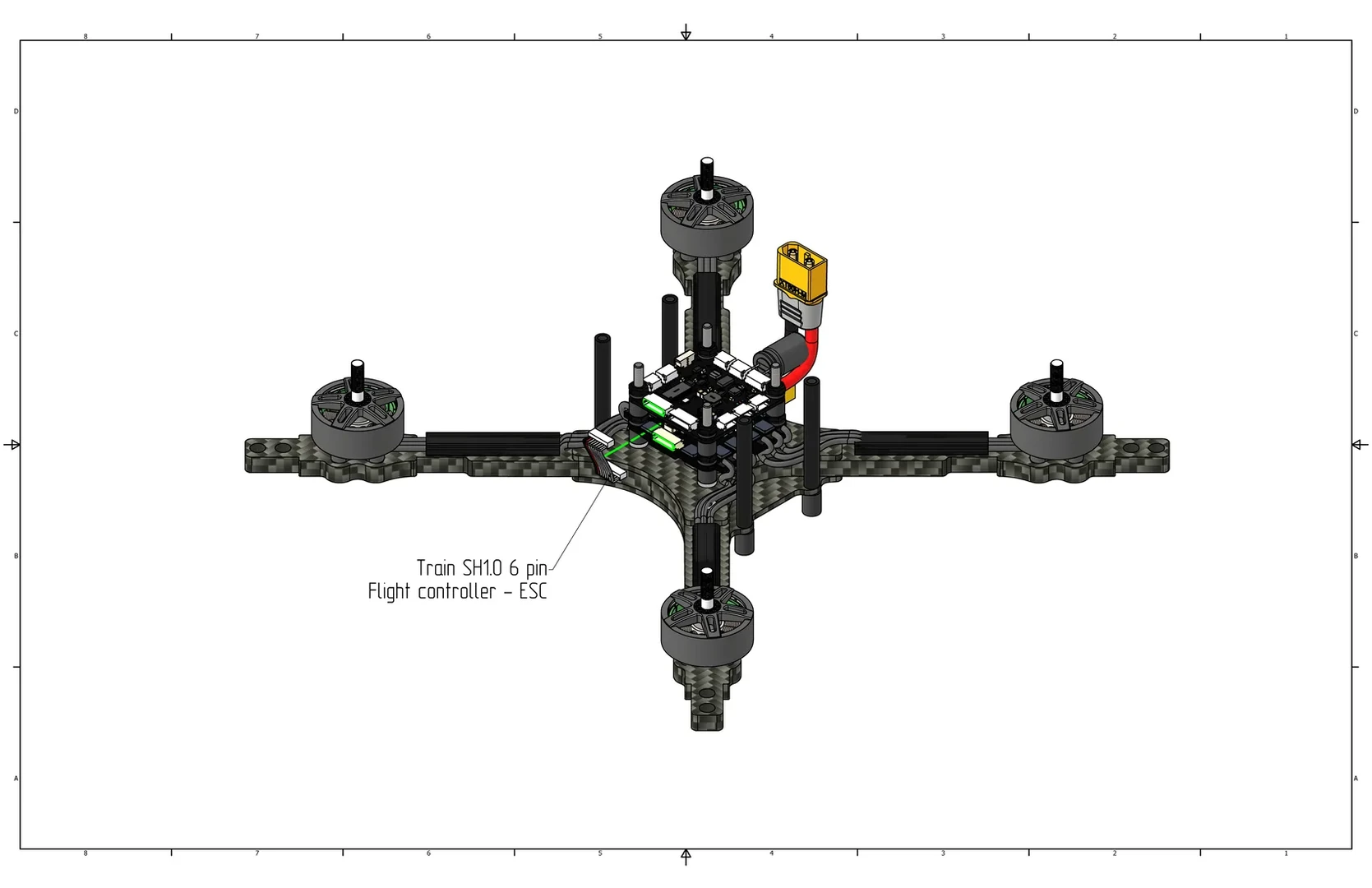
View with the cable installed.
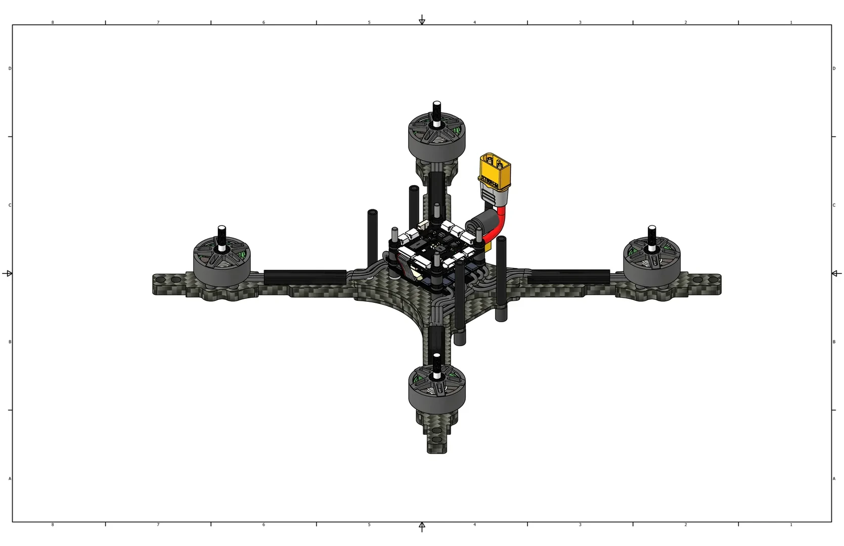
Raspberry Pi Installation
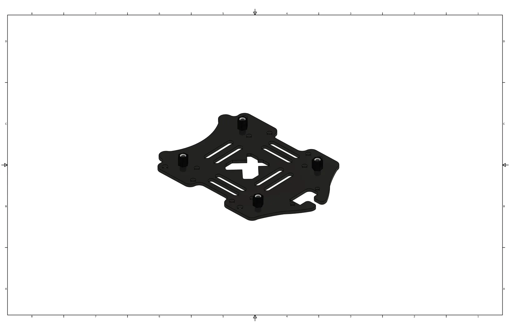
Install M2.5 standoffs (Cell 3) on the polycarbonate mounting plate using M2.5x4 screws (Cell 17).
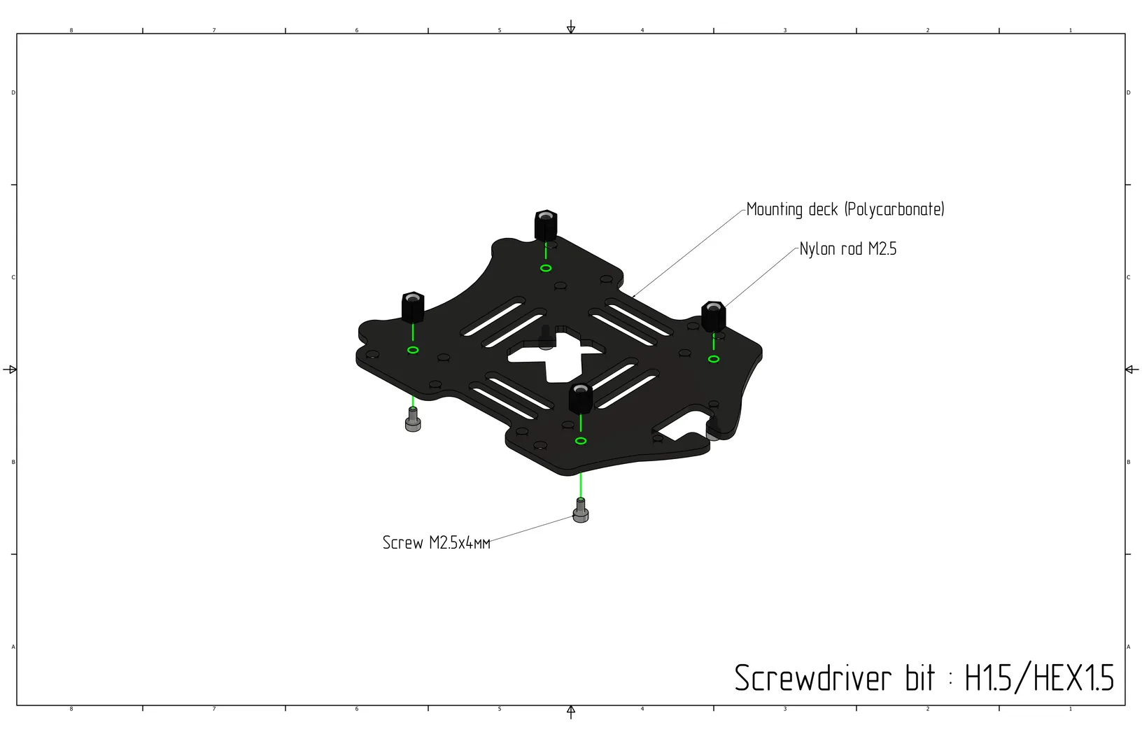
Tighten the screws. Use an H1.5/HEX1.5 bit.
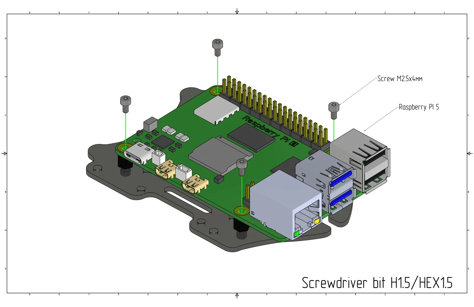
Place the Raspberry Pi 5 on top of the M2.5 standoffs and secure the Raspberry Pi 5 board using M2.5x4 screws (Cell 17).
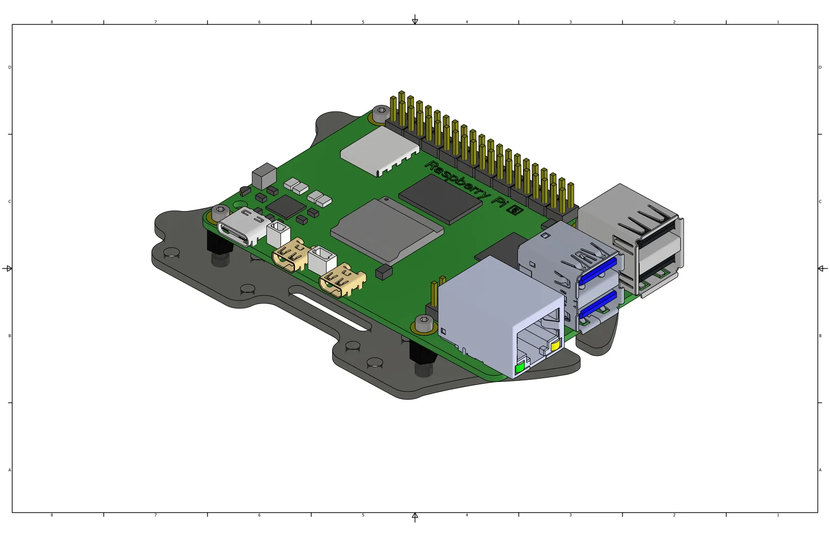
View with the Raspberry Pi 5 installed.
Remove the films from the thermal pads and place them in the positions highlighted in the image. Install the cooling heatsink on the Raspberry Pi by inserting the locking clips through the heatsink into the Raspberry Pi. Connect the cooling system to the port marked in the image.
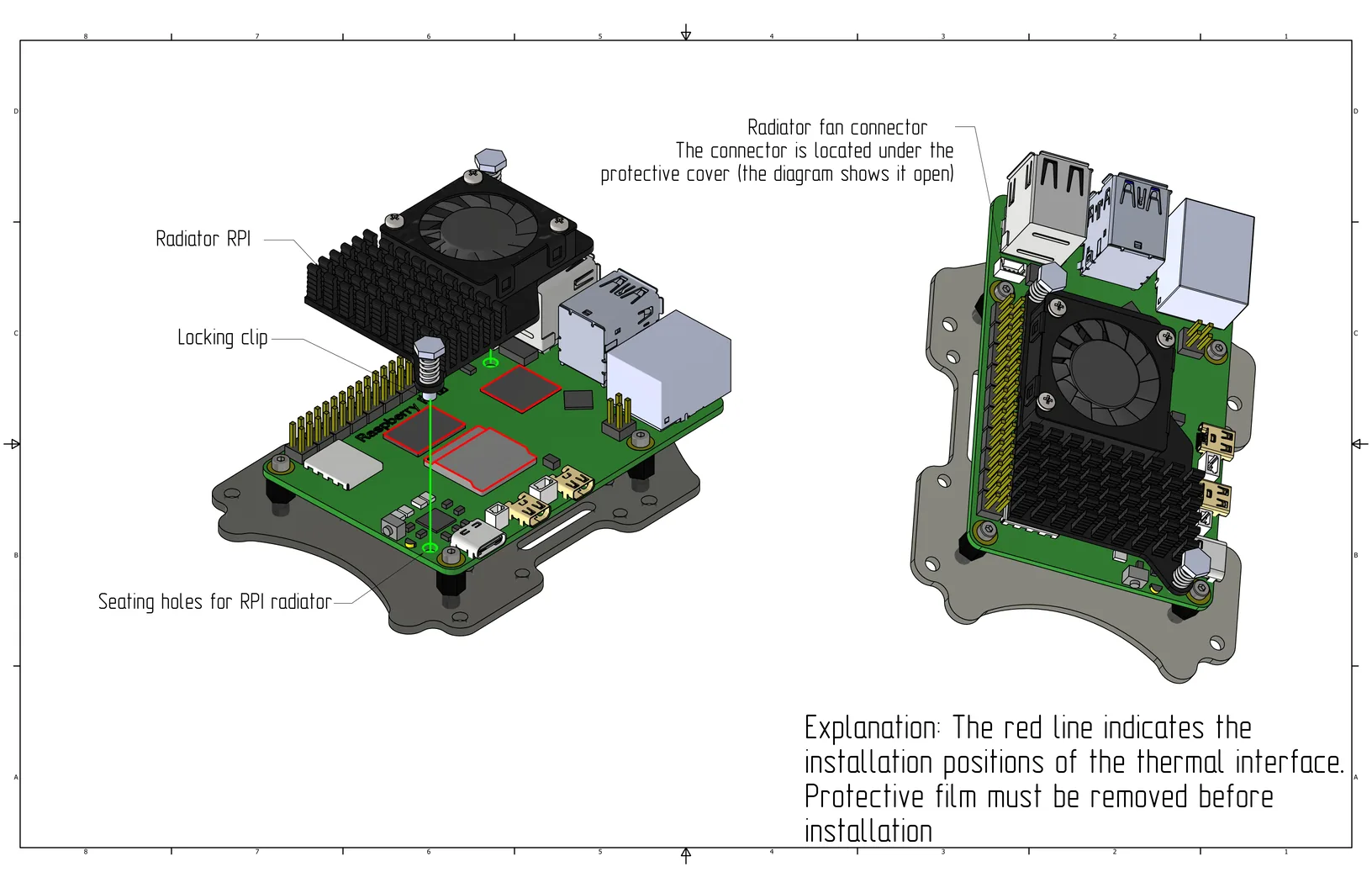
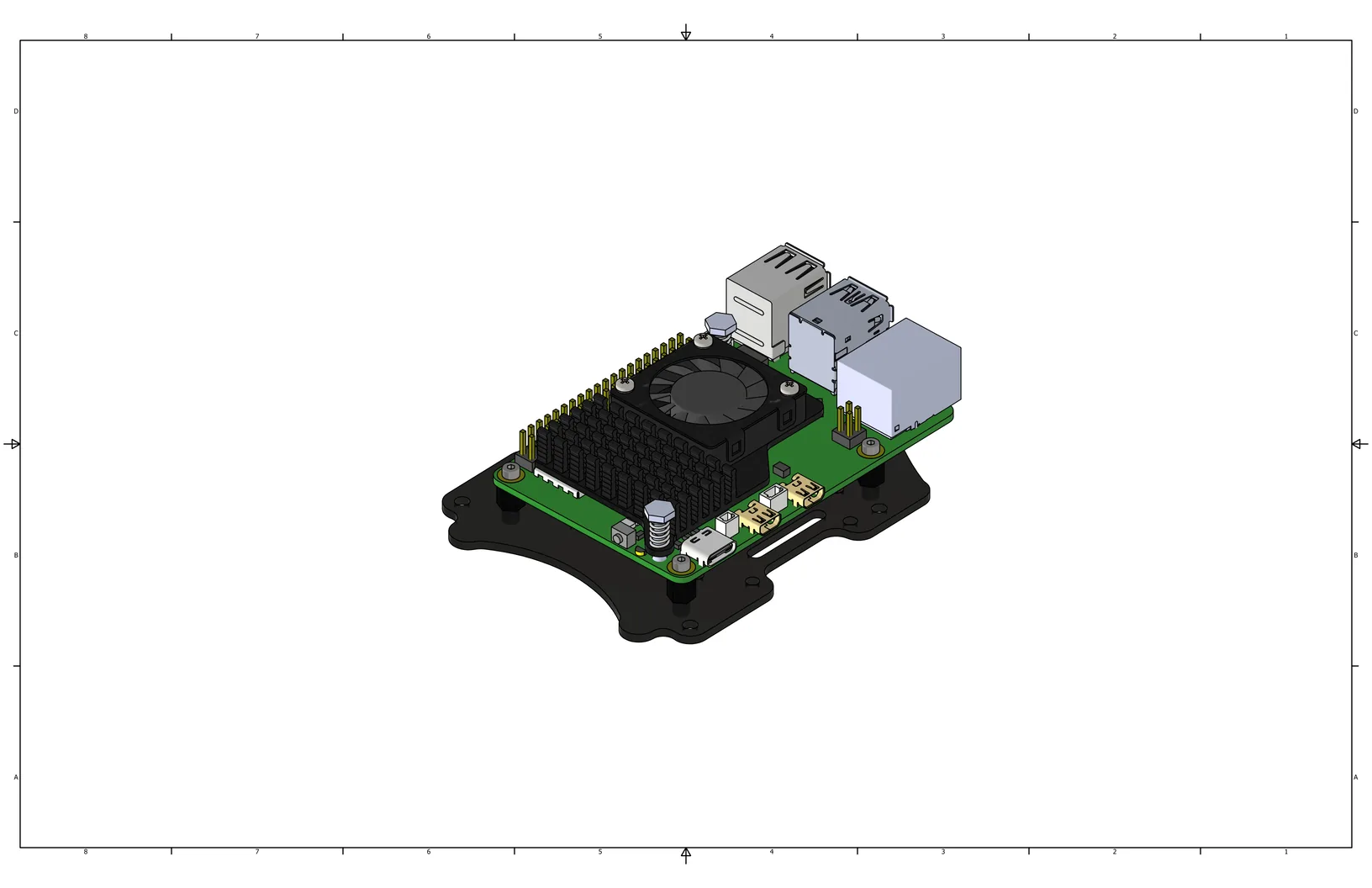
Raspberry Pi with heatsink assembled.
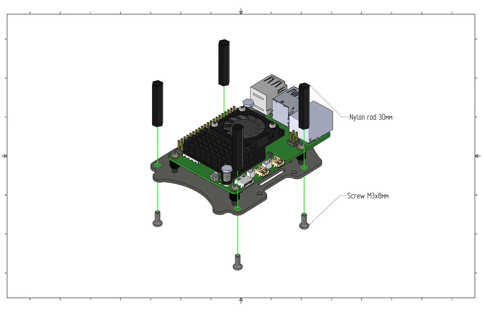
Install 30mm nylon standoffs (Cell 21) on the plate with the Raspberry Pi using M3x8 screws (Cell 8).
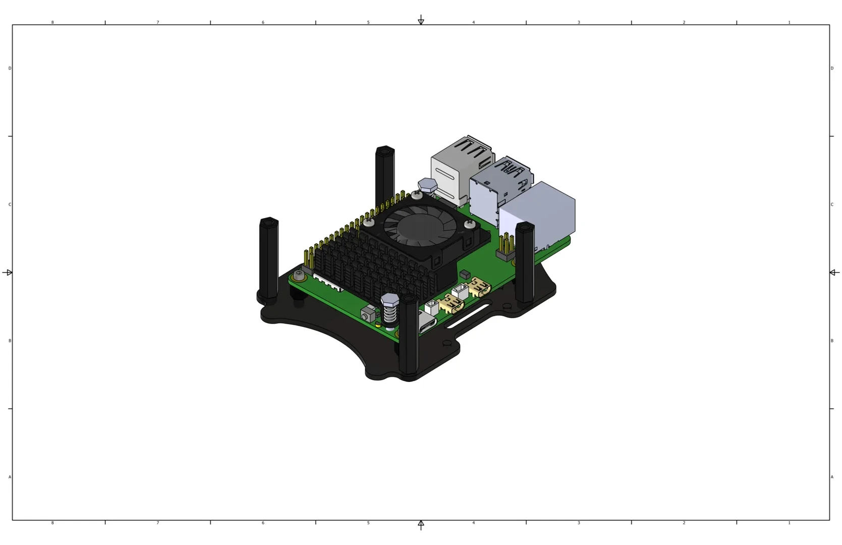
View with nylon standoffs installed.
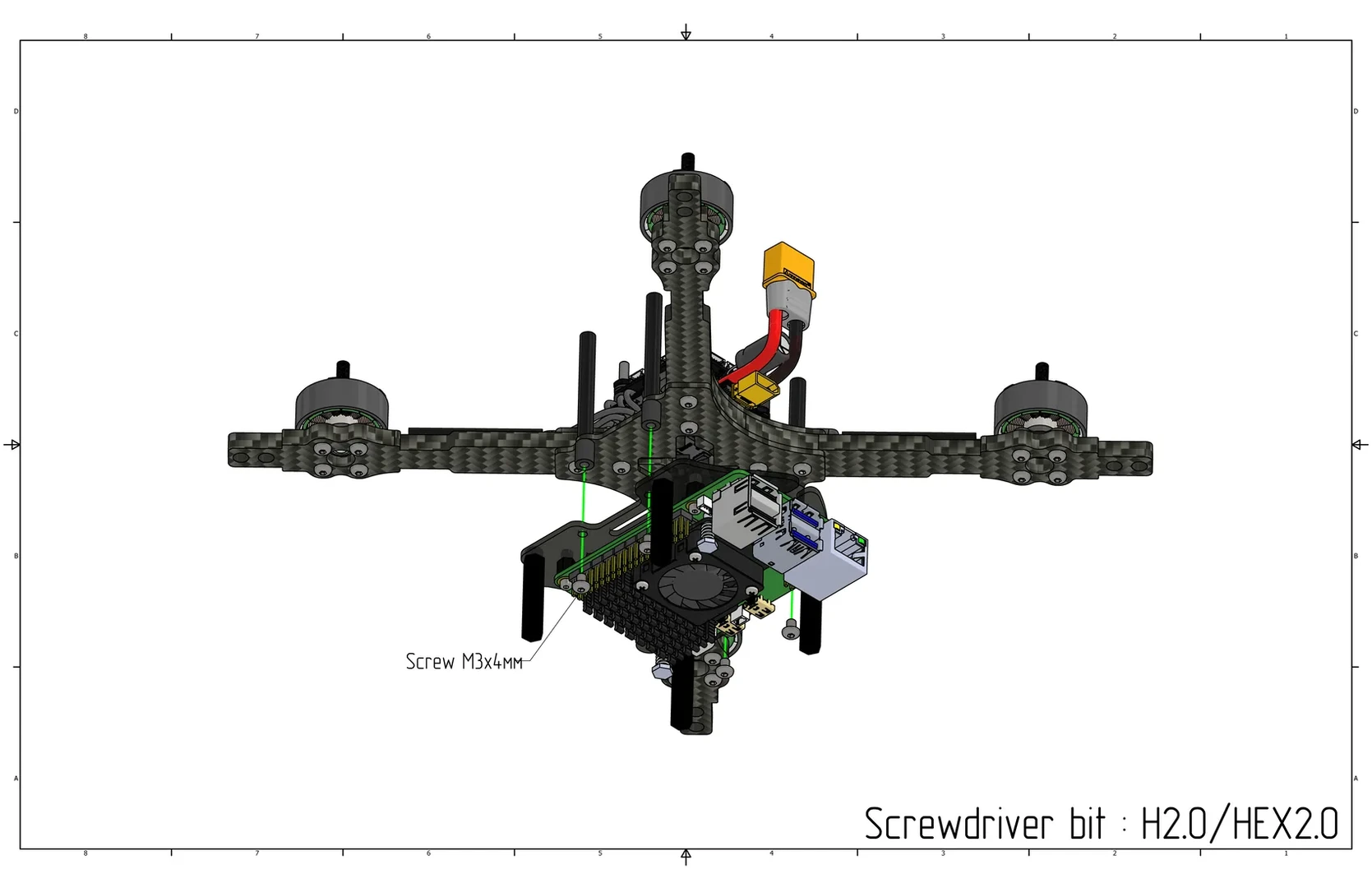
Install the assembled plate with the Raspberry Pi onto the bottom part of the quadcopter onto the damper standoffs, secure with M3x4 screws (Cell 10).
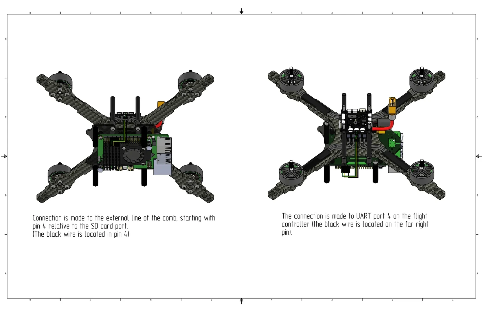
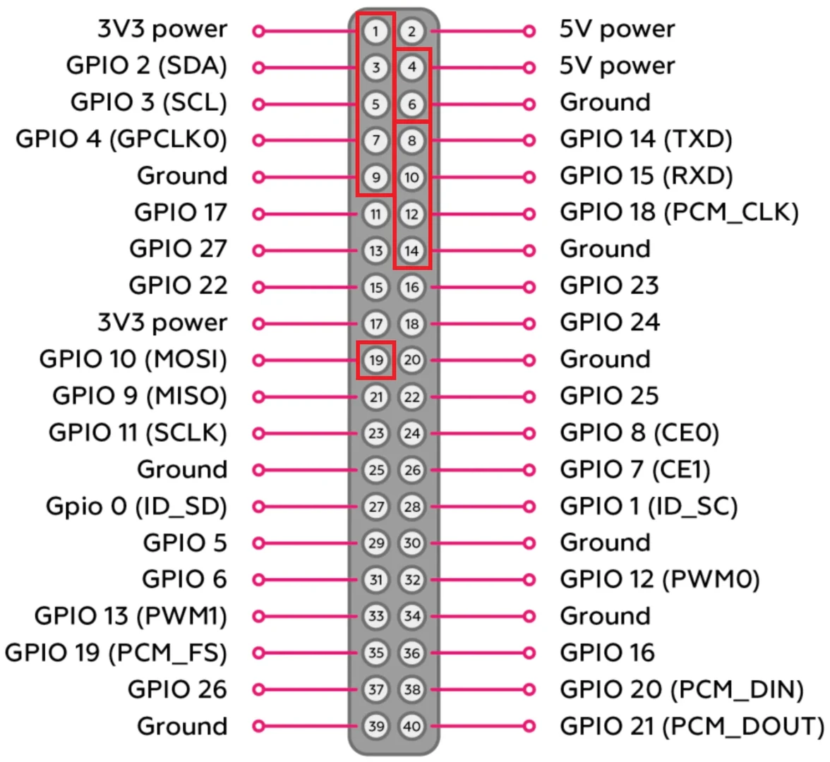
Connect the data cable to the Raspberry Pi. The connection is made to the outer row of the header, starting from the 4th port relative to the SD card port (black wire in port 14, see pinout). The other end connects to the UART 4 port on the flight controller (black wire is located in the far right corner).
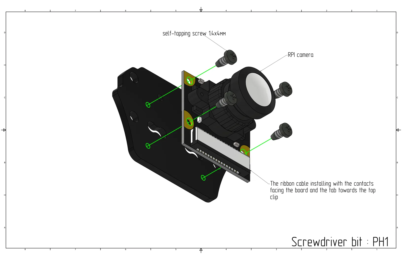
Install the camera on the small mounting plate with the tab towards the top clip and secure it using two M1.4x4 self-tapping screws (Cell 19) in the top left and bottom right corners. Assembly bit: PH1.
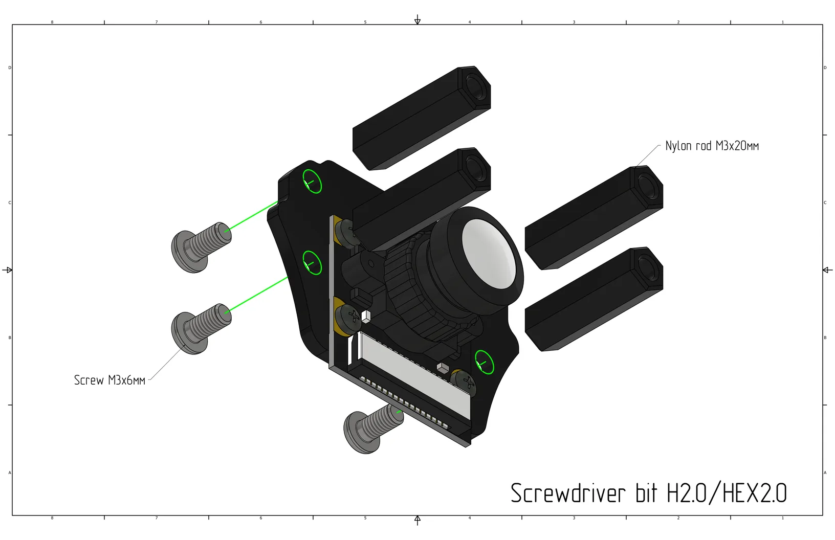
Install 20mm nylon standoffs (Cell 22) on the small mounting plate and secure with M3x6 screws (Cell 9).
Install the small mounting plate with the camera onto the gripper plate using M3x6 screws (Cell 9).
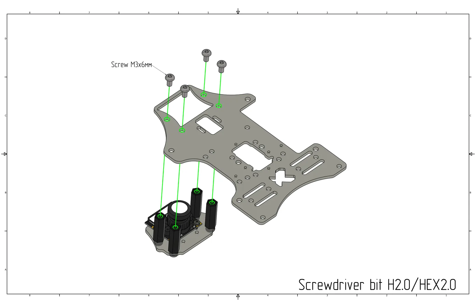
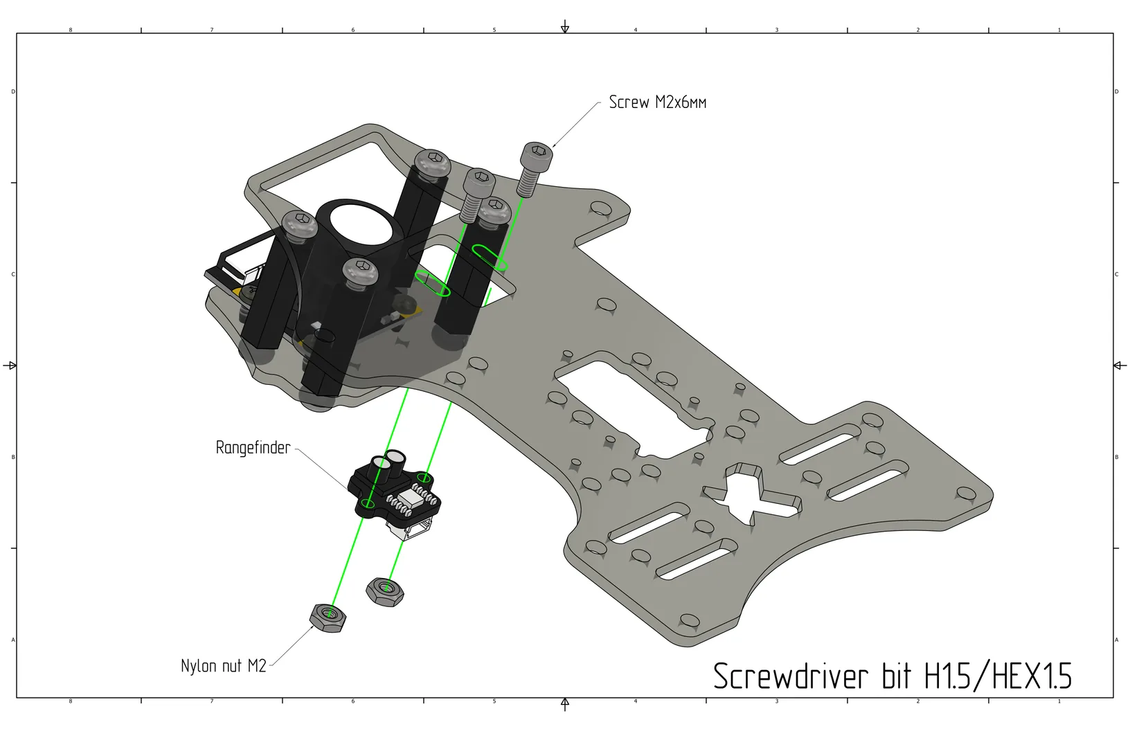
Install the laser rangefinder on the gripper plate using M2x6 screws (Cell 16) and M2 nylon nuts (Cell 5).
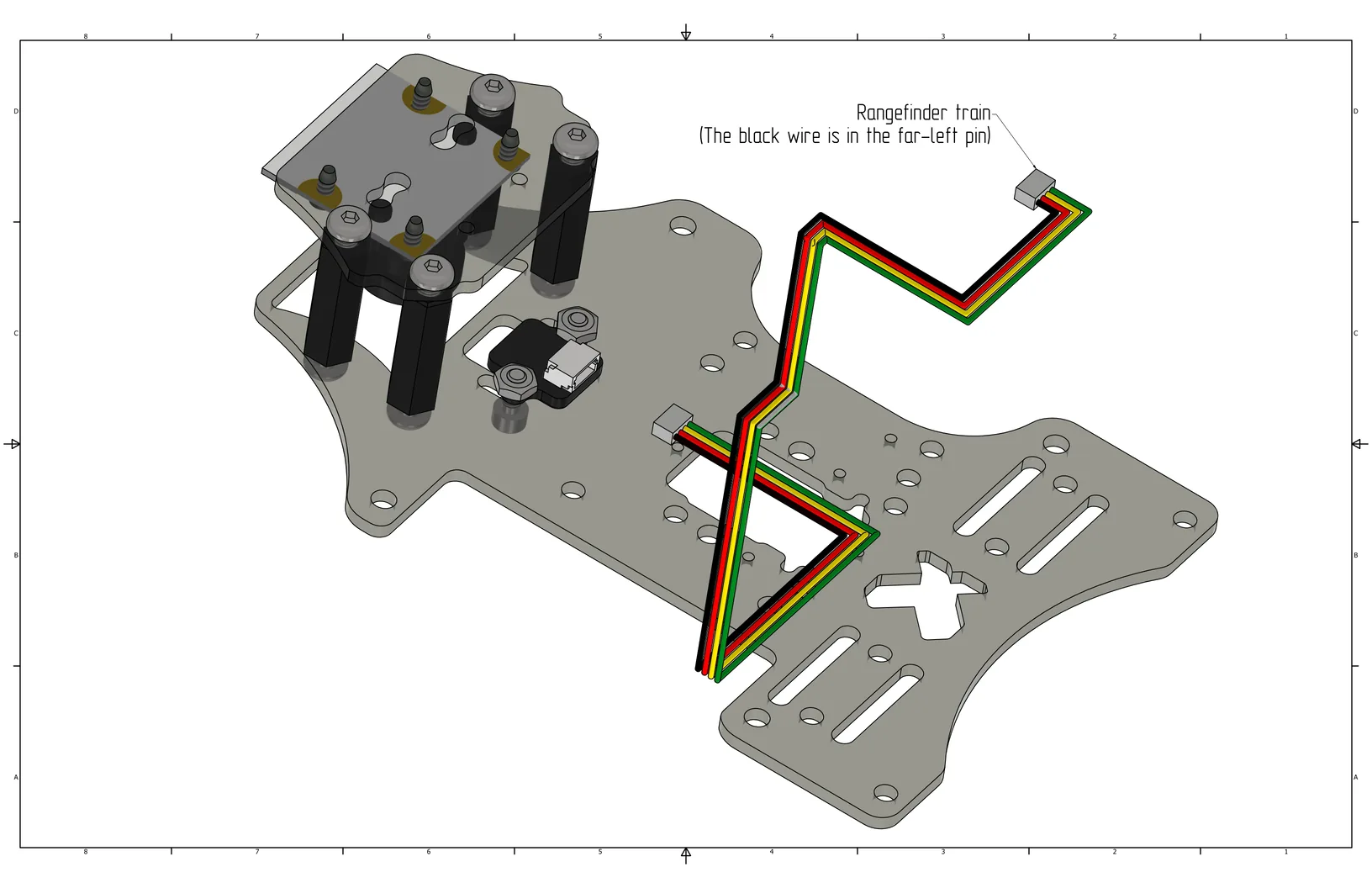
Connect the laser rangefinder cable.
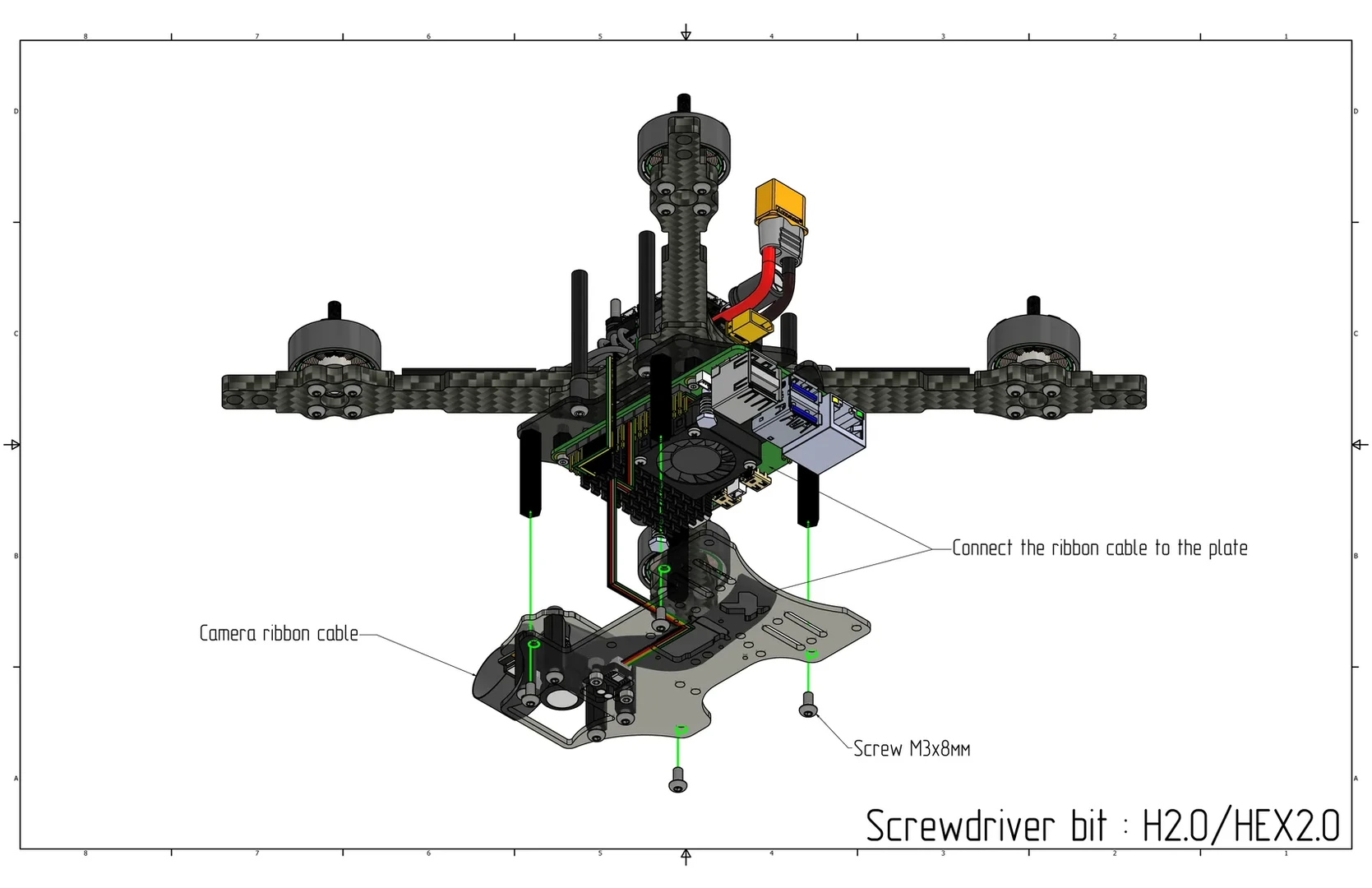
Install the gripper plate on the quadcopter using M3x8 screws (Cell 8).
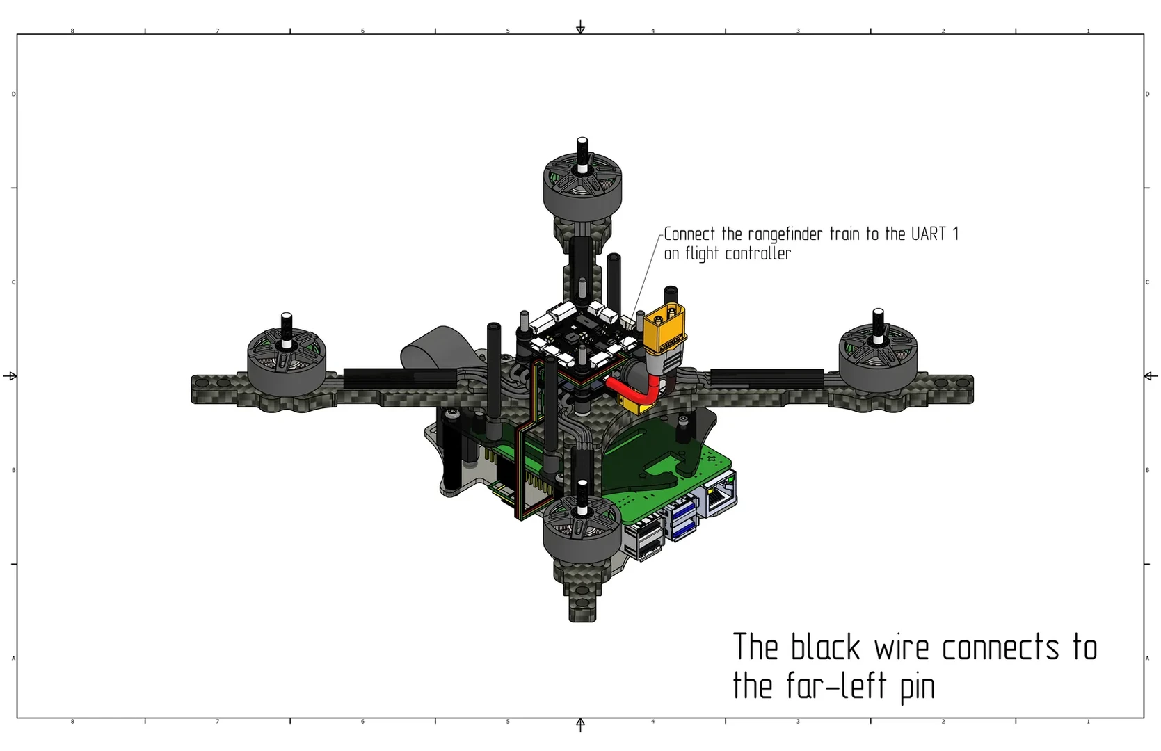
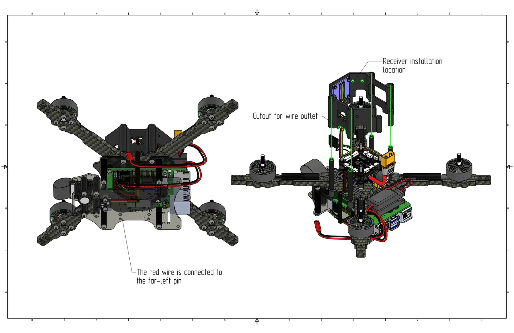
Connect the rangefinder cable to the UART 1 port on the flight controller (black wire in the far left pin).
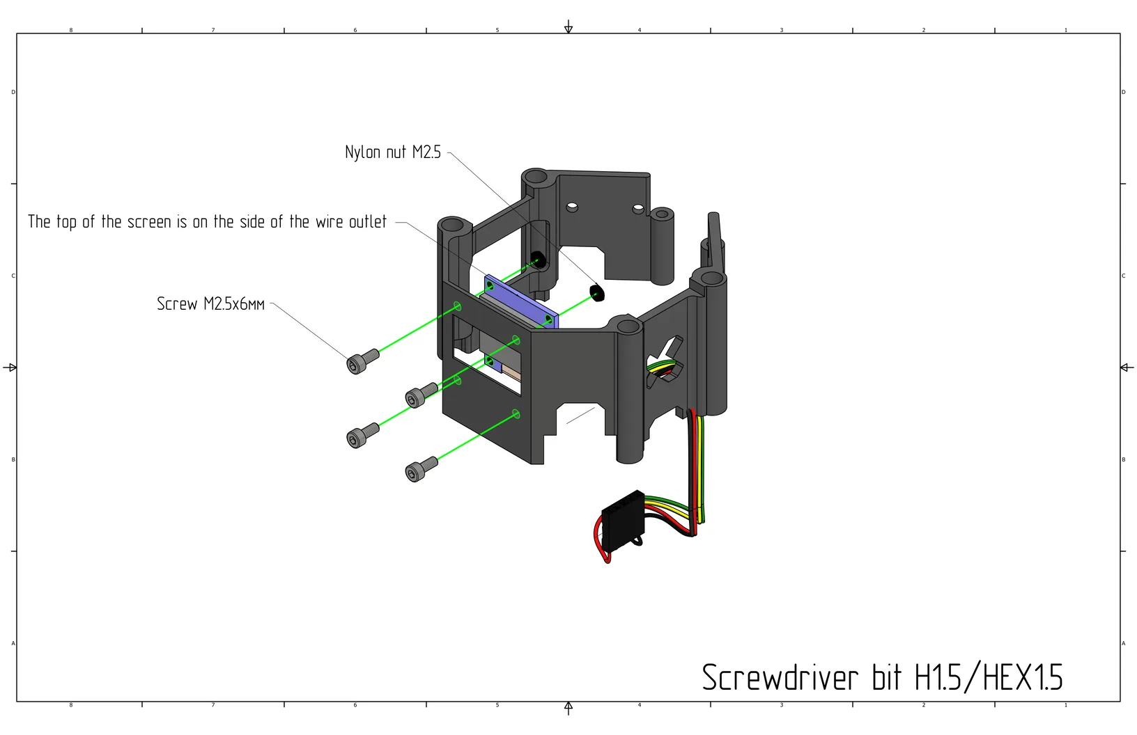
Install the screen on the drone canopy using M2.5x6 screws (Cell 18) and M2.5 nylon nuts (Cell 4).
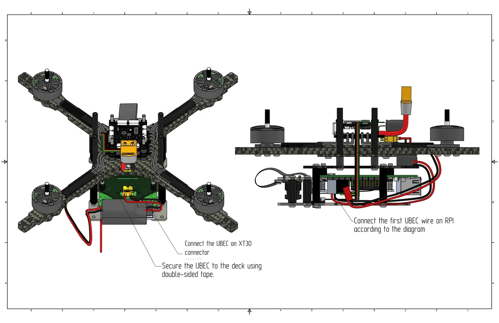
Solder a Dupont connector to one UBEC and a JST connector to the other. On the other side, join the input wires and solder the XT30 connector. Glue the UBECs together using double-sided tape.

Install the UBEC on the plate with the Raspberry Pi using double-sided tape. Connect the UBEC to the ESC via the XT30 connector. Connect the first UBEC wire to the Raspberry Pi as indicated in the picture (pins 4 and 6, see pinout above).
Connect the receiver to the SBUS/CRSF (UART 6) port on the flight controller (black wire in the far left pin).
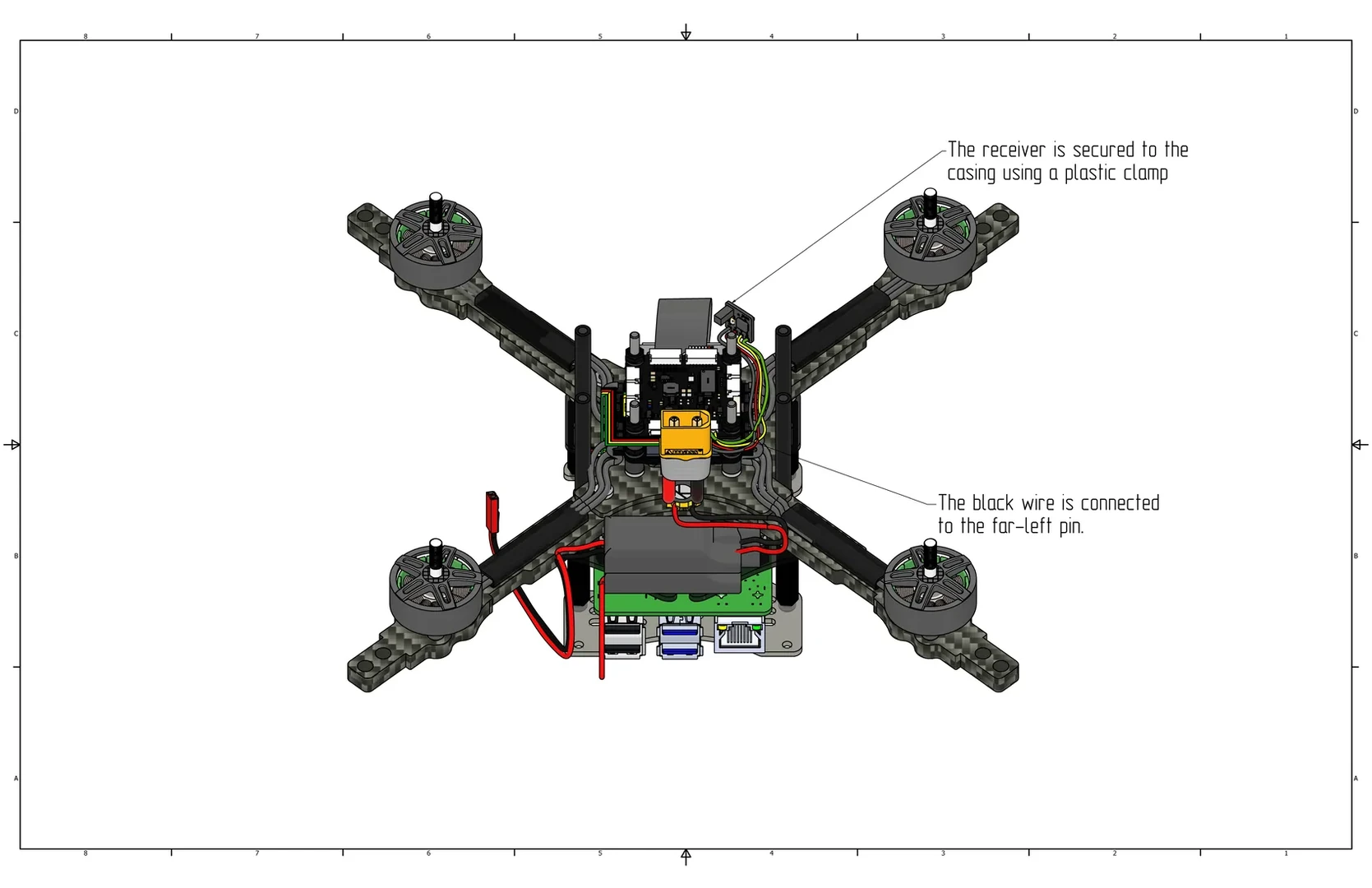
Install the canopy over the aluminum standoffs and secure the receiver with a zip tie into the highlighted holes in the image. Route the wires into the wire cutout in the canopy. Connect the screen to the Raspberry Pi; the red wire connects to the far left pin of the inner row of the header relative to the SD card (red - pin 1, black - pin 9).
Installing Guards, Legs, and LED Strip
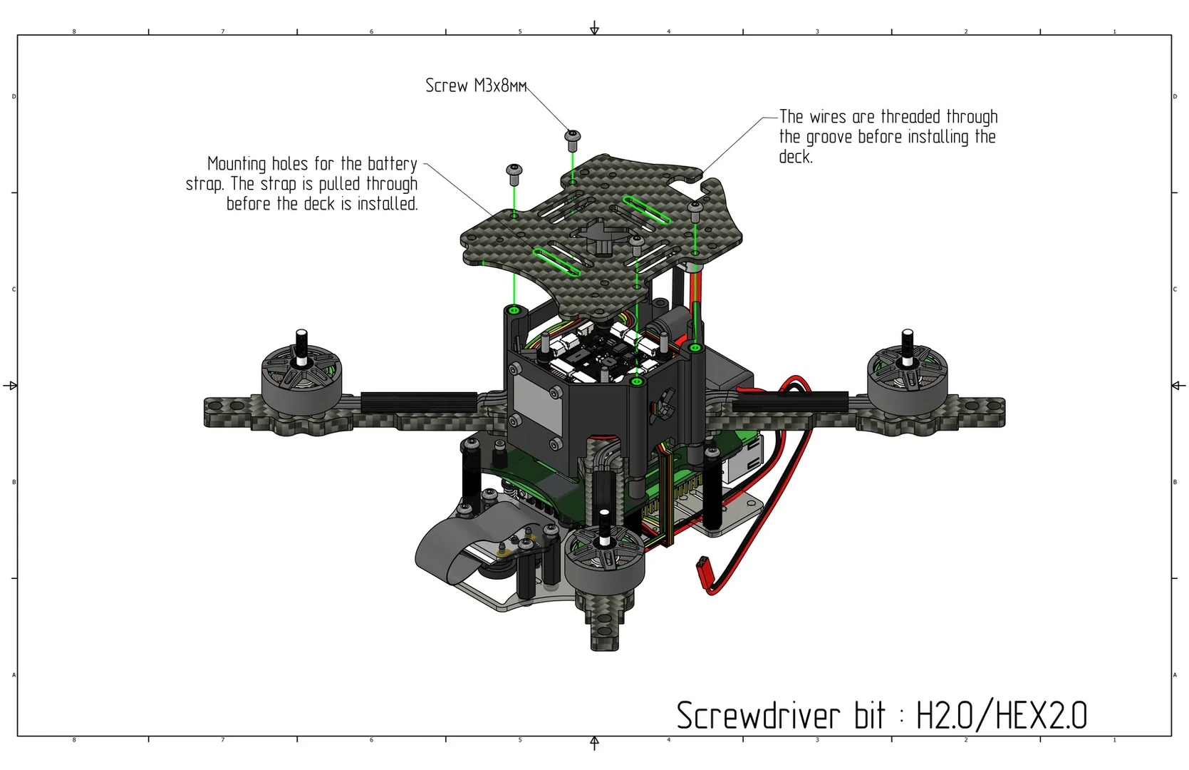
Thread the strap into the top plate, then secure it to the aluminum standoffs using M3x8 screws (Cell 8), and secure the power connector using M2.5x6 screws (Cell 18). Assembly bit for the plate - H2.0/HEX2.0, for the connector - H1.5/HEX1.5.
Arrange the guard bridges in a square at the bottom, then place the bottom guard arcs on the corners, secure with M3x10 screws (Cell 13) from the top, and 40mm nylon standoffs (Cell 23) from the bottom.
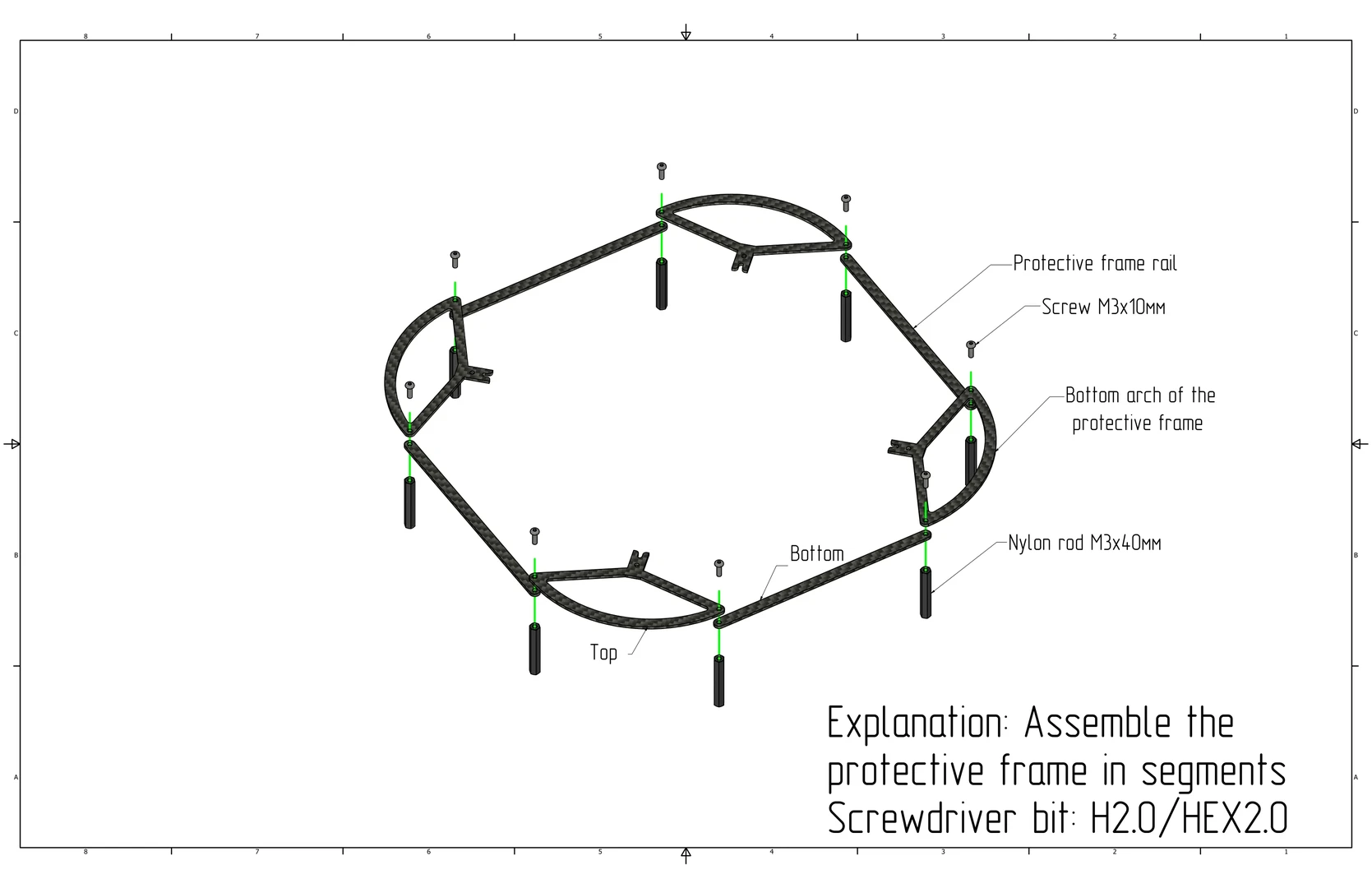
Secure the top arcs and bridges in reverse order using M3x8 screws (Cell 8); the bridges should face inward and the arcs outward.

Install and secure M3 press nuts (Cell 1) into the holes at the ends of the arms.
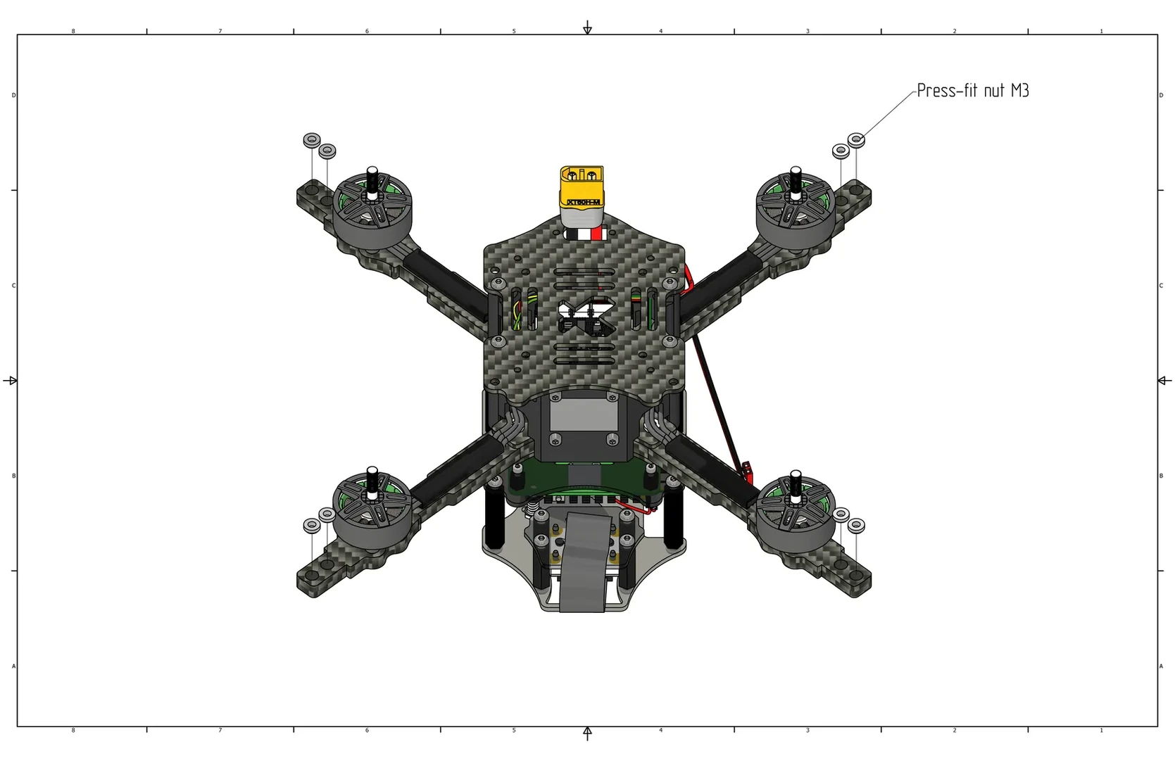
Install the guard from the bottom side and secure it using M3x10 screws (Cell 13).

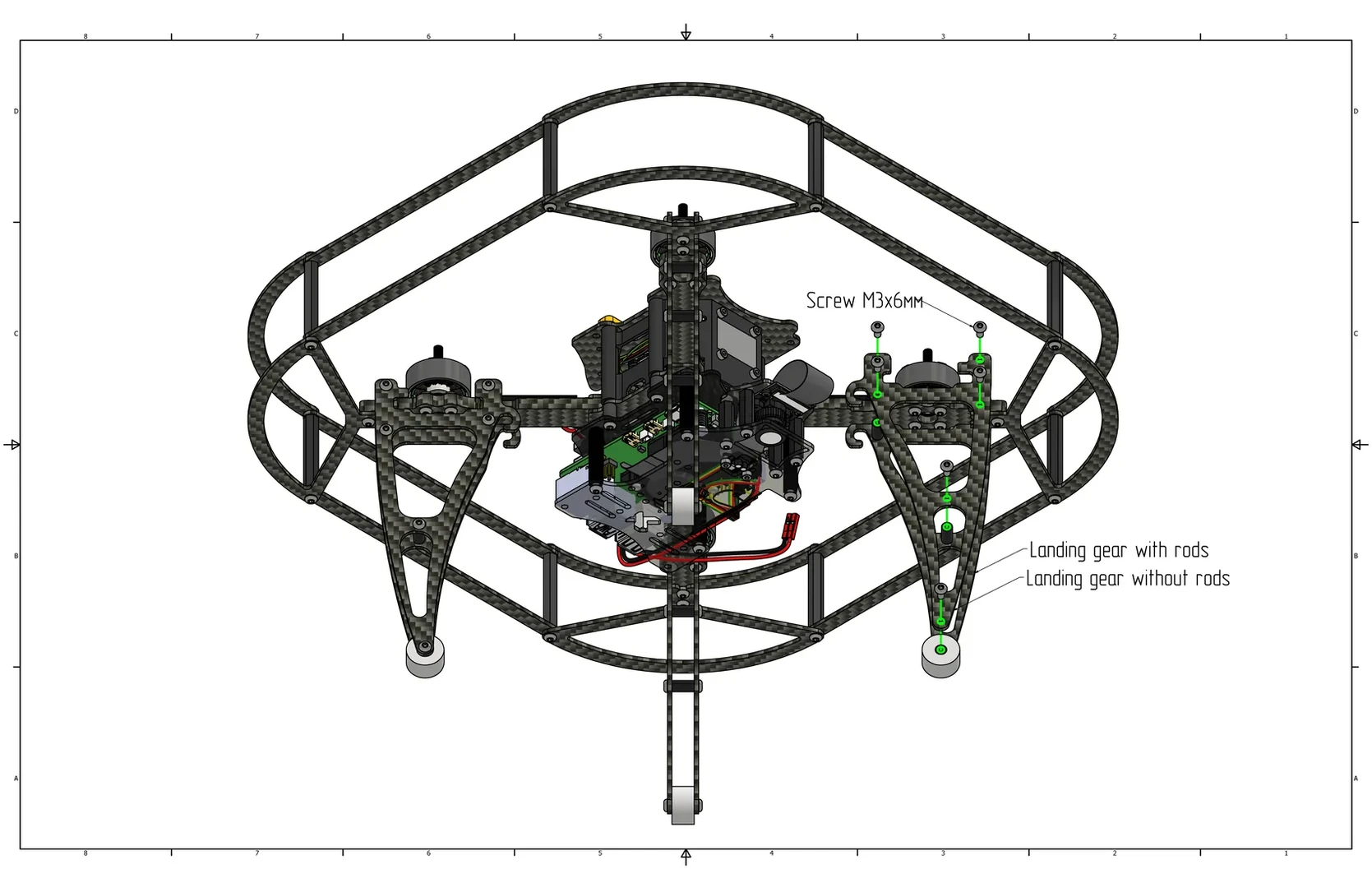
Screw M3x6 screws (Cell 9) into all holes on one side of the large leg, and secure them with 10mm aluminum standoffs (Cell 14) on the other side. Place a TPU foot (spacer) (Cell 25) over the standoff in the bottom hole.

Place the large leg on the arm as shown in the image and secure with M3x6 screws (Cell 9). Do the same for the other legs.
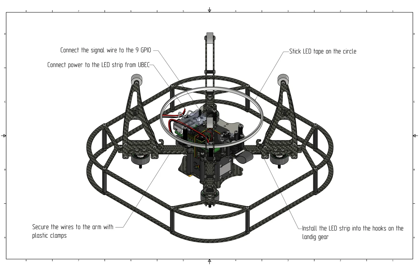
Stick the LED strip onto the circumference (plastic ring for the strip), then install it into the hooks on the legs and secure the wires with a zip tie. Connect the power to the second free UBEC, and connect the signal wire to GPIO 9 (pin 21).
Install the propellers according to the classic rotation direction, as shown in the image.

Caution
Check that no components remain unsecured. Before the first power-on, ensure that the propellers do not touch the canopy or wires.