Clover 5 FPV
Contents
Fastener Sizes
Tip
Fasteners of various sizes are used during assembly. Installing screws or standoffs of the wrong size may result in damage to the quadcopter.
Cell 1 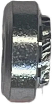
Press Nut M3 |
Cell 2 
Nylon Nut M3 |
Cell 3 
Nylon Standoff M2.5 |
Cell 4
Nylon Nut M2.5 |
Cell 5
Nylon Nut M2 |
Cell 6 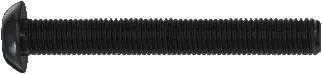
Screw M3x40 |
Cell 7 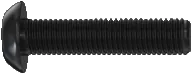
Screw M3x12 |
Cell 8 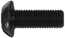
Screw M3x8 |
Cell 9 
Screw M3x6 |
Cell 10 
Screw M3x4 |
Cell 11 
Aluminum Standoff M3x40 |
Cell 12 
Damper Standoff M3 |
Cell 13 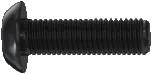
Screw M3x10 |
Cell 14 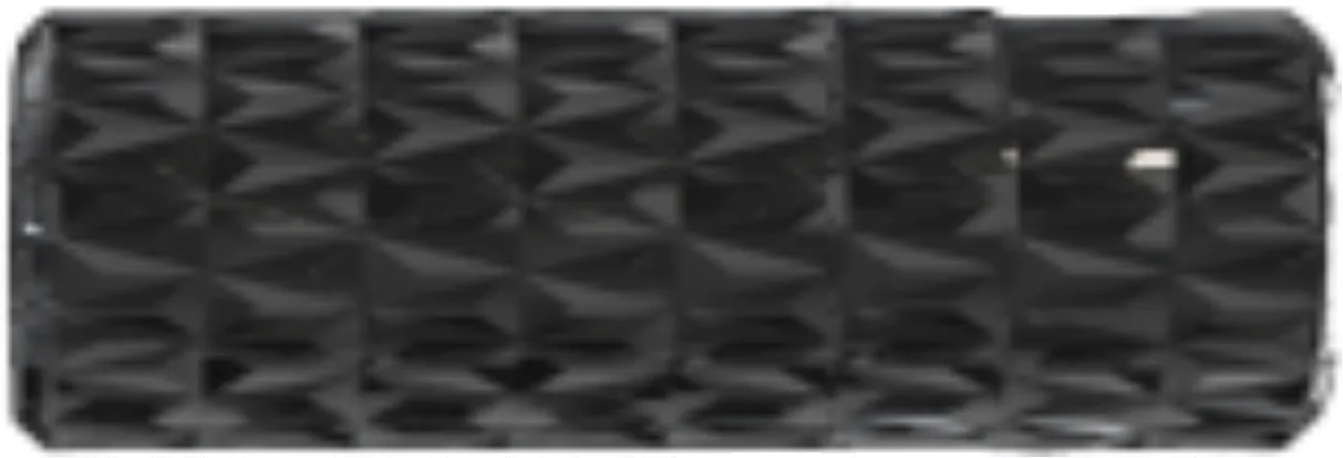
Aluminum Standoff M3x10 |
Cell 15
Aluminum Standoff M3x30 |
Cell 16 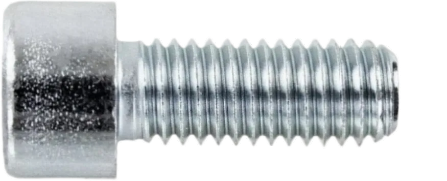
Screw M2x6 |
Cell 17 
Screw M2.5x4 |
Cell 18
Screw M2.5x6 |
Cell 19 
Self-tapping Screw M1.4x4 |
Cell 20
Screw M2x3 |
Cell 21 
Nylon Standoff M3x30 |
Cell 22 
Nylon Standoff M3x20 |
Cell 23 
Nylon Standoff M3x40 |
Cell 24 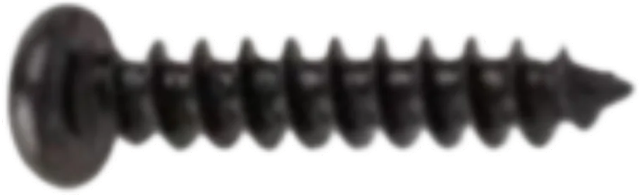
Self-tapping Screw M1.4x10 |
Cell 25 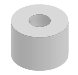
TPU Foot |
Frame Assembly
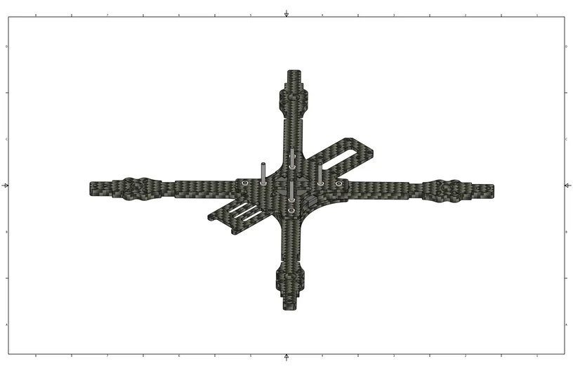
Align the 4 arms between the middle and bottom plates, installing the spacer between them.

Install M3x12 screws (Cell 7) and M3x40 screws (Cell 6) from the bottom plate side: M3x12 (Cell 7) in the outer arm holes, M3x40 (Cell 6) in the central holes of the bottom plate.
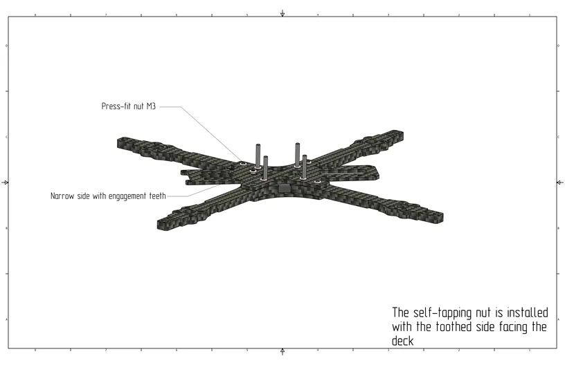
Install M3 press nuts (Cell 1) on the middle plate and secure them with screws.
Motor Installation
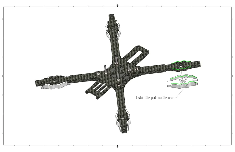
Install the arm guards as shown in the image.
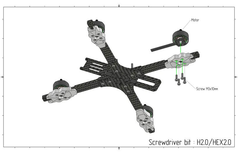
Install the motors into the corresponding holes on the arm using M3x10 screws (Cell 13).
Caution
Ensure that the motors are secured with M3x10 screws; otherwise, a short circuit between the windings may occur.
ESC Installation
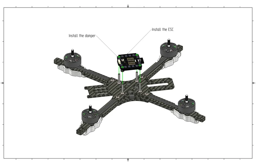
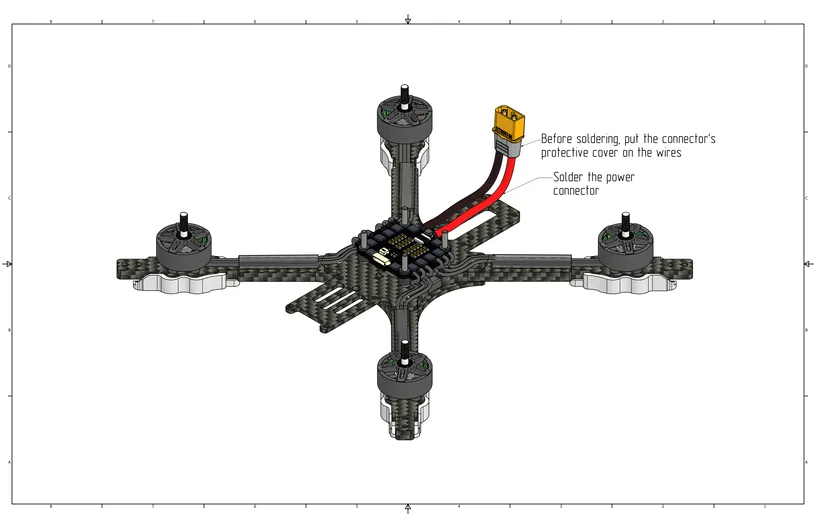
Install the Electronic Speed Controller (ESC) over the M3x40 screws (Cell 6) on the middle plate. The battery power contacts should face backward.
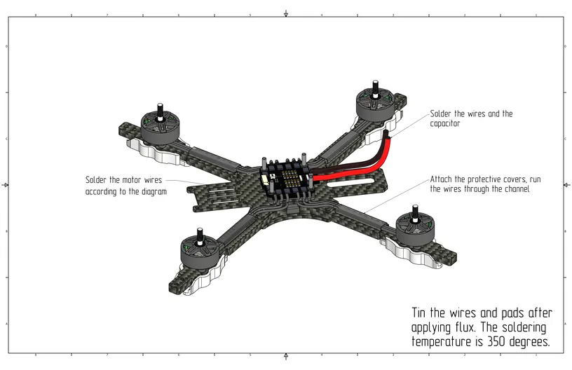
Glue the protective covers and thread the motor wires through them. Solder the power wires and the capacitor to the ESC power pads, and solder the motors to the motor pads (see image below).
Slide the protective cover onto the power wires, then solder the XT60 power connector. Snap the protective cover onto the power connector.
Flight Controller Installation
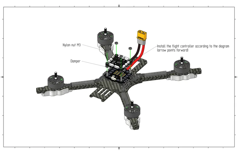
Install the flight controller with the arrow pointing forward, then install M3 nylon nuts (Cell 2) to secure the flight controller.
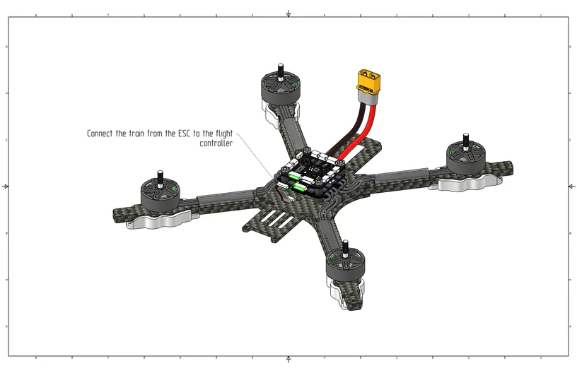
Install the 6-pin cable between the flight controller and the ESC.
Video Transmitter Installation

Quadcopter Assembly
Install M3x30 aluminum standoffs (Cell 15) on top, and secure them from the bottom using M3x6 screws (Cell 9).
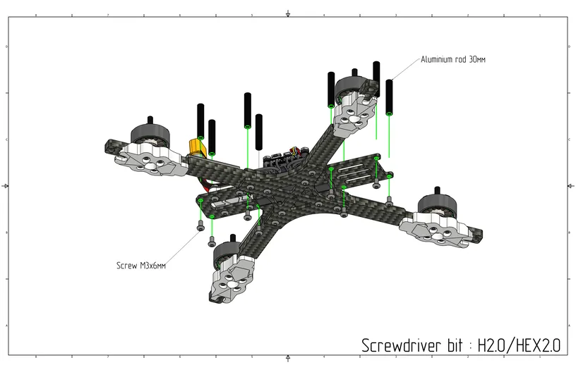
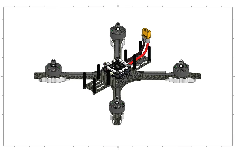
View with aluminum standoffs installed.
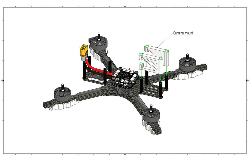
Install the camera mount on the front standoffs as shown in the image below.
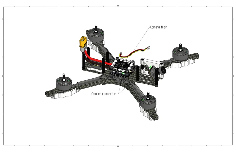
Install the video camera into the mount using M2x3 screws (Cell 20) and secure it at your preferred camera tilt angle.

Connect the camera cable to the camera port on the flight controller, as shown in the image.
Install the connector into the antenna mount and tighten it using a propeller wrench (8mm wrench), then connect the antenna connector to the video transmitter and install it on the rear standoffs.

Install the ELRS radio receiver and connect it using the cable to the SBUS/CRSF port on the flight controller.
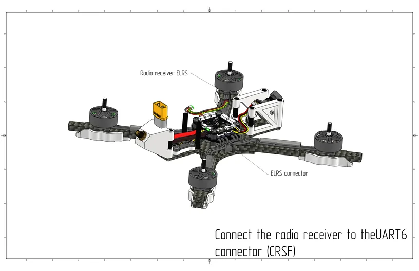
Install the rear protective guards by hooking them onto the standoff near the flight controller and snapping the clip onto the rear standoff.
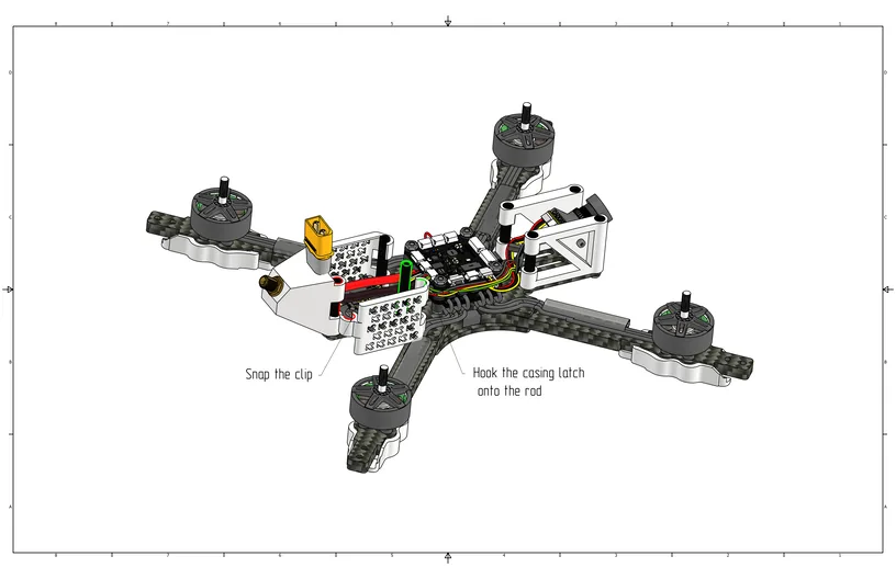
Install the LED modules by sticking them with double-sided tape onto the inner sides of the arms (see image below).

Connect the LED modules to the hub as shown in the image. Connect the hub to the LED/Buzzer port on the flight controller.
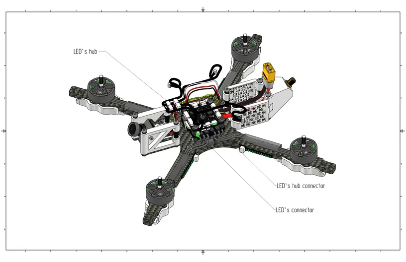
Route the wires from the LED modules as shown in the image.
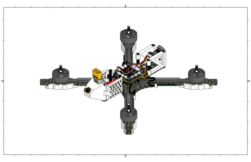
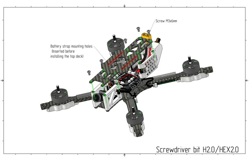
Thread the battery strap through the mounting slots, and install the top plate using M3x6 screws (Cell 9).
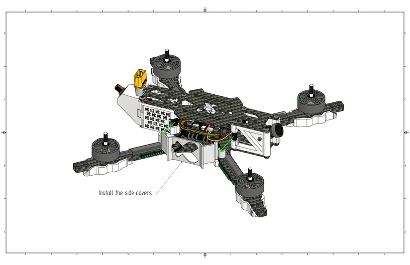
Install the side guards on the central standoffs and snap them onto the guard clips.
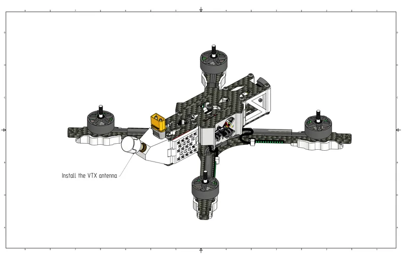
Screw the video antenna onto the connector at the rear.
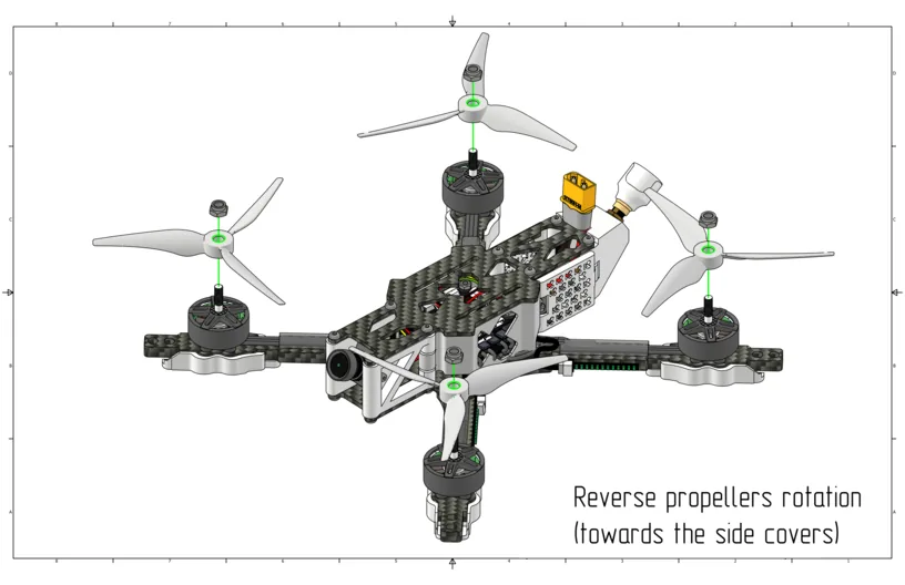
Install the propellers according to the reversed rotation direction (“props out”), as shown in the image.
Caution
Check that no components remain unsecured. Before the first power-on, ensure that the propellers do not touch the canopy or wires.